Window comparator
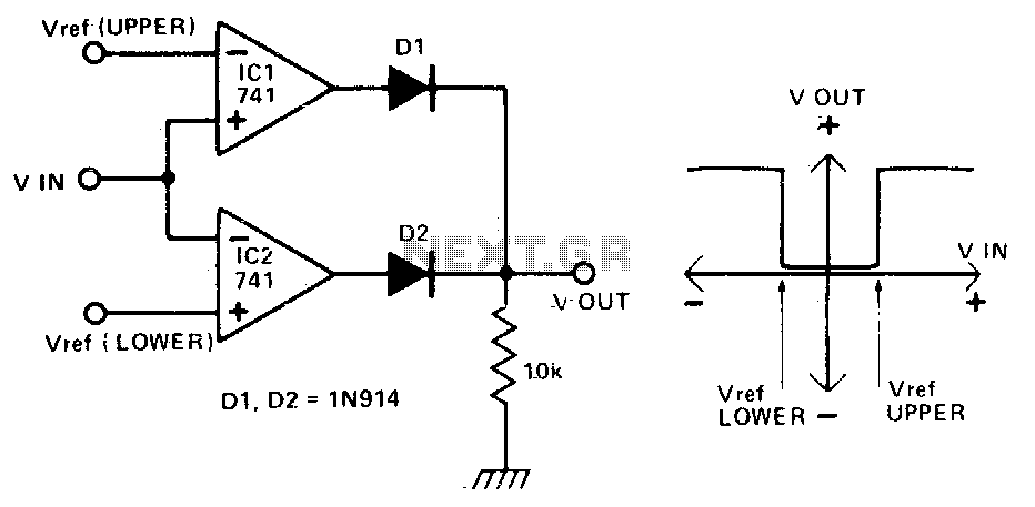
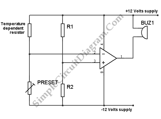
This circuit produces an output of 0V when the input voltage is within a specified range defined by two reference voltages. When the input voltage falls outside this range, the output becomes positive. Two operational amplifiers (op-amps) function as voltage comparators. If the input voltage (Vin) exceeds the upper reference voltage (Vref upper), the output of the first op-amp (IC1) is positive, causing diode D1 to become forward biased. Conversely, if Vin is less than Vref upper, the output of IC1 is negative, resulting in D1 becoming reverse biased, and thus the output voltage (Vout) is 0V. Similarly, if Vin is less than the lower reference voltage (Vref lower), the output of the second op-amp (IC2) is positive, making diode D2 forward biased and Vout positive. If Vin is greater than Vref lower, Vout returns to 0V. When Vin remains within the range set by the reference voltages, Vout is maintained at 0V.
This circuit serves as a window comparator, effectively monitoring the input voltage against two predetermined thresholds. The operational amplifiers are configured in a comparator mode, where they compare the input voltage against the upper and lower reference voltages. The reference voltages can be set using precision voltage dividers or reference voltage sources to ensure accuracy.
In this configuration, the output states are determined by the relationship between Vin and the reference voltages. The positive output states are achieved through the conduction of the diodes, which are strategically placed to control the flow of current based on the op-amp outputs. The use of diodes ensures that the output voltage is only positive when the conditions are met, effectively isolating the output from the input during the inactive state.
The circuit can be utilized in various applications, such as in safety systems, where it is critical to maintain the input voltage within a specific range to avoid damage or malfunction. Additionally, it can be employed in signal conditioning applications where monitoring and controlling voltage levels are necessary to ensure proper operation of subsequent circuitry. The design can be further enhanced by incorporating hysteresis to prevent oscillation around the reference voltages, improving stability and response time in dynamic environments.This circuit gives an output (which in this case is OV) when an input voltage lies in between two specified voltages. When it is outside this window, the output is positive. The two op amps are used as voltage comparators. When Vin is more positive than Vref (upper) the output of ICl is positive and D1 is forward biased. Otherwise the output is negative, D1 reverse biased and hence Vout is OV. Similarly, when Vin is more negative than Vref (lower), the output of IC2 is positive; D2 is forward biased and this Vout is positive
Otherwise Vout is OV. When Vin lies within the window set by the reference voltages, Vout is OV.
