
Windshield wiper control
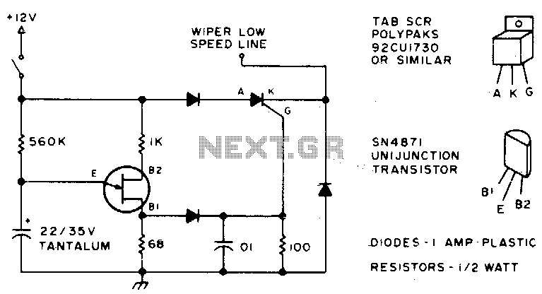
The interval wiper circuit provides an efficient way to manage the operation of windshield wipers, allowing them to operate intermittently rather than continuously. The circuit typically involves a timer IC, such as the NE555, configured in astable mode to generate a pulse-width modulation signal. The two connections to the car's wiper control allow the circuit to interface directly with the existing wiper motor control system.
The ground connection is essential for establishing a common reference point for the circuit. The use of a potentiometer (500 K) in conjunction with a fixed resistor (100 K) enables the user to adjust the interval timing of the wipers. By varying the resistance, the timing can be tailored to suit different weather conditions or personal preferences.
In practical implementation, the circuit may include additional components such as diodes for protection against back EMF generated by the wiper motor, as well as capacitors to stabilize the power supply and filter out noise. The choice of components should be made with consideration of the specific vehicle's electrical characteristics to ensure compatibility and reliability.
Overall, this circuit design offers a straightforward solution for enhancing windshield wiper functionality, providing drivers with improved visibility during adverse weather conditions.Here"s a good way to set windshield wipers on an interval circuit. Only two connections to the car"s wiper control, plus ground, are required Variable control can be accomplished by substituting a 500 K pot in series with a 100 K fixed resistor in place of the 560 K. 🔗 External reference
Related Circuits
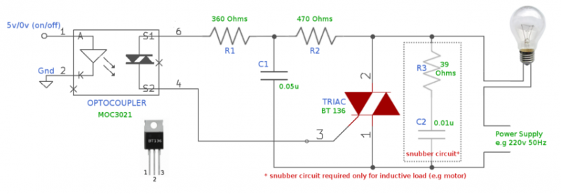
For many years, electromagnetic relays have been utilized as switches for controlling high-voltage devices. However, due to their large size and the noise they produce (both electrical and mechanical), TRIACs combined with opto-couplers have emerged as a more effective...
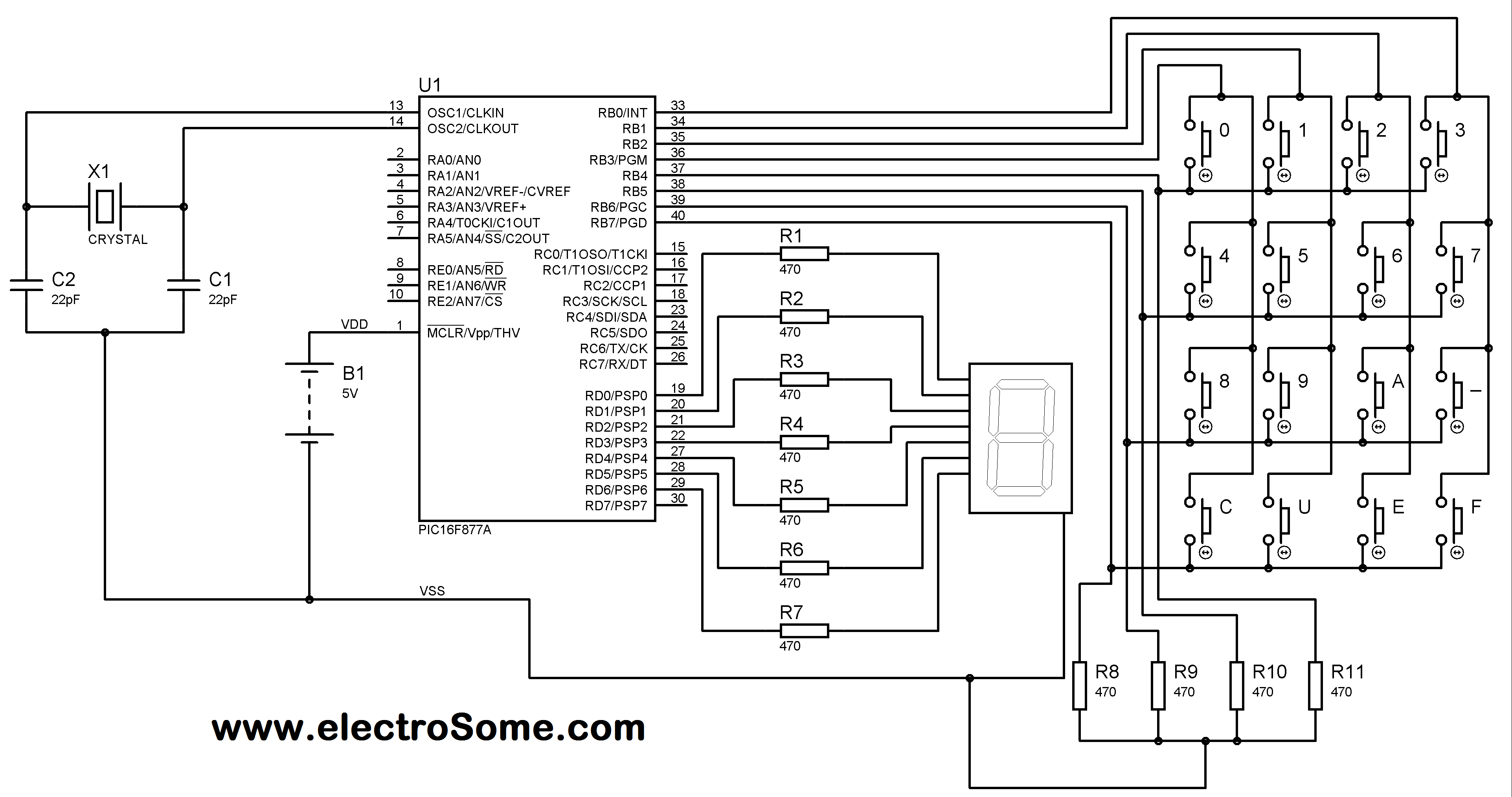
A matrix keypad is a highly useful and user-friendly component in the design of applications such as calculators and telephones. It consists of push-button switches arranged in rows and columns. For instance, interfacing a 4x4 (16 keys) matrix keypad...
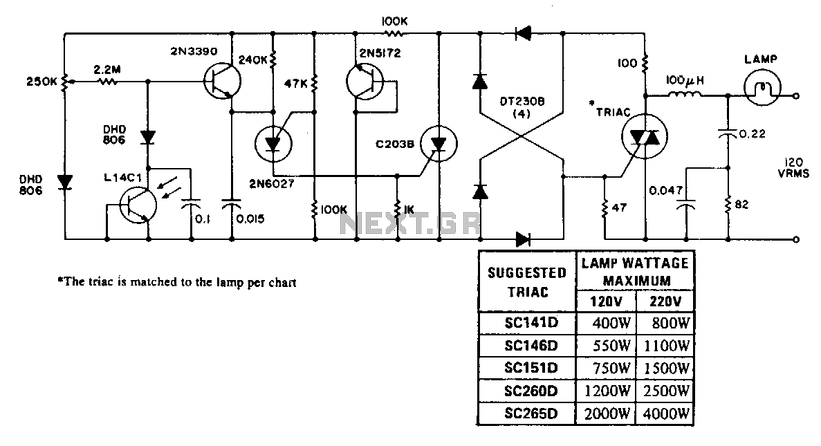
An automatic control maintains a lamp at a constant brightness over a wide range of supply voltages. This circuit utilizes the consistency of photodiode response to control the phase angle of power line voltage applied to the lamp and...
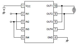
A simple forward-reverse motor control driver electronic circuit can be designed using the LB1948M, a two-channel low saturation voltage forward-reverse motor control driver IC. The LB1948M motor driver is suitable for use in 12V system products and can drive...
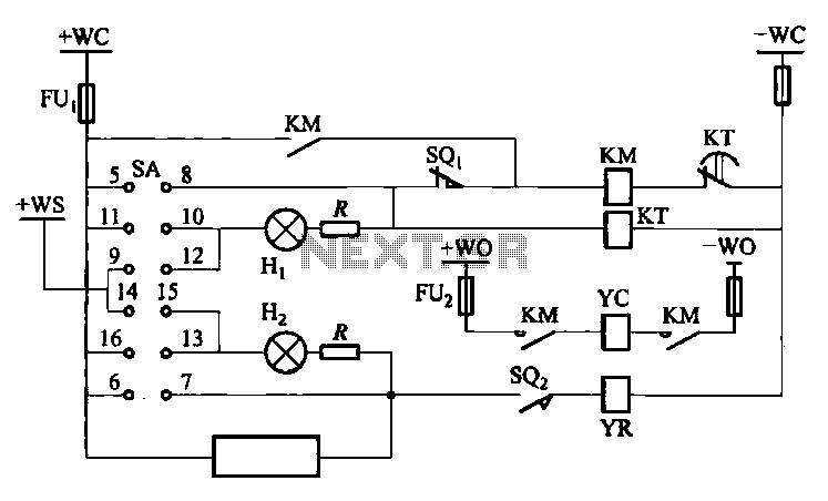
The DW10M de-excitation type switch is based on the DW10 automatic air circuit breaker, transitioning from normally open to normally closed contact. The models available include DW10M-200, DW10M-400, and DW10M-600. The control circuit for this type switch is illustrated...
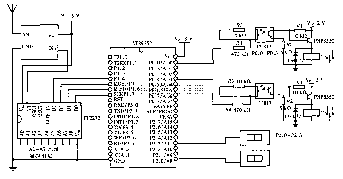
This design aims to create a long-distance wireless remote control switch lighting control system, which consists of a transmission system and a reception system. The system utilizes wireless transceiver modules for RF transmission and reception. The transmitting portion mainly...