
With self-locking function of the forward start circuit

The circuit design presented involves a control mechanism for lighting systems, where SBi serves as the activation switch to initiate the operation of the run lights (Hi). Upon pressing SBi, the circuit completes, allowing current to flow to the Hi lights, which illuminate to indicate that the system is active. Conversely, the SB2 button functions as a deactivation switch, interrupting the flow of current and extinguishing the run lights when pressed.
The down lights, represented by Hz, can be integrated into the circuit to provide additional lighting control. These lights can be configured to operate independently or in conjunction with the run lights, depending on the desired application. The circuit design may include additional components such as resistors, capacitors, and transistors to manage the current flow and ensure stable operation of the lighting system.
It is important to note that while the general indicator circuit is not depicted in the schematic, it can be included to provide visual feedback regarding the operational status of the system. This can enhance user experience by indicating whether the system is active or inactive through LED indicators or similar devices.
Overall, this circuit serves as a fundamental control system for managing lighting operations, with the potential for further expansion and integration of additional features as required by the specific application. Circuit shown in FIG. 3 + 20. Figure, SBi as the start button, SB2 is the stop button, Hi to run lights, Hz as down lights. In the circuit described later, in order to avoid te dious, general indicator circuit is not shown.
Related Circuits
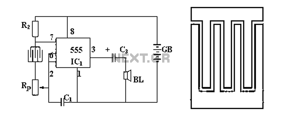
Figure 1 illustrates a circuit diagram related to an audio circuit that incorporates a resistance between two leads connected to a rain alarm probe. Figure 2 demonstrates the connection of a capacitor to the probe within the audio circuit....
The circuit consists of a light metering circuit and a flash circuit, as illustrated in the accompanying image. It is designed for use with integrated cameras such as POPTICS, Franka X-500, and WIZEN-860S. The circuit includes the following components:...
The objective is to enhance information transmission by utilizing articles. Please contact us via email at [email protected] within 15 days if there are issues related to article content, copyright, or other concerns. Prompt action will be taken to resolve...
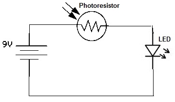
A simple photoresistor circuit will be constructed to demonstrate the operation of a photoresistor, which activates the circuit in the presence of light and deactivates it in darkness. This circuit connects a photoresistor to an LED. When the photoresistor...
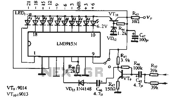
The circuit features a manual recording level control function. When in recording mode, the recording level is indicated by the LM3915N. The sound recording circuit, as illustrated in Figure 3-17, employs an RC network and an associated audio recording...
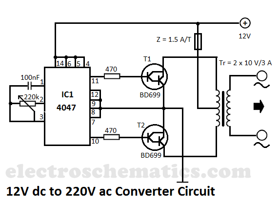
This DIY 12V to 220V voltage converter is built with the CMOS 4047, which serves as the main component of this compact voltage converter that transforms 12V DC into 220V AC. The 4047 is configured as an astable multivibrator,...