
Recording level display circuit
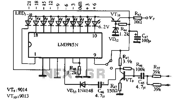
The circuit is designed to facilitate the recording and playback of audio signals with precision and flexibility. The LM3915N serves as a visual indicator, providing real-time feedback on the recording level, which is crucial for achieving optimal audio quality. The RC network, in conjunction with the audio recording preamplifier, helps to prepare the audio signal for processing, ensuring that it is appropriately amplified before being recorded.
During playback, the equalization circuit plays a vital role in adapting the output signal to match the characteristics of the tape used. The three distinct equalization settings cater to different tape formulations—chromium and metal—allowing for tailored playback that compensates for frequency response variations inherent to each tape type. The switch IC2a enables seamless transitions between these settings, enhancing user convenience.
The recording equalization network, utilizing components such as C12, R19, C13, and Q4, ensures that both low and high frequencies are accurately represented in the recorded signal. This is essential for maintaining audio fidelity and ensuring that the playback sound matches the original recording as closely as possible.
The inclusion of manual control via potentiometer RP3 allows the user to fine-tune the recording level, providing additional control over the audio input. This feature is particularly beneficial in environments where varying sound levels are present, enabling the user to adjust the recording level to prevent distortion or loss of detail in the audio.
The push-pull high-frequency magnetic bias oscillation circuit, operating at a frequency of 90 kHz, is critical for both erasing previous recordings and ensuring that new audio signals are recorded with clarity. The LC filter used in the power supply for this circuit helps to stabilize the oscillation frequency, which is vital for consistent performance across different recording sessions.
Overall, this circuit design integrates various components and features to enhance the recording and playback experience, providing flexibility, precision, and adaptability to different tape types and recording environments.Provided only manual recording level control function, when the circuit is in the recording mode, the recording level as LM3915N was shown. 3-180 as shown in Figure 3-17 in the sound recording circuit by IC] RC network and related audio recording preamplifier circuit. In playback features common with (NOr) equalization circuit, with chromium (Cr02) and metal (Met) with three different tape playback equalization network network, controlled by switch o IC2a etc.
playback voltage amplifier , to adapt the level of the input amplifier circuit requirements. IC2b and related network of recording equalization network, for ordinary tape and C12 composed by the R17RisCl1 low frequency compensation network, high-frequency compensation by R19, , Cl3, q4 composition o for chromium metal band and high frequency band, is only for compensation, C15 -, C16 and R2l composed of high-frequency compensation chrome band, C17.CIS Biao and high compensation network consisting of a metal band. RP3 potentiometer to manually adjust the recording level. High-frequency transformer T and VTi, VTz composed push-pull high frequency magnetic bias oscillation circuit, the oscillation frequency is 90kHz ;.
The bias magnetic oscillator on the one hand to provide the erase erase head bias current, the other for audio recording heads for sound recording bias current. In order to ensure the stability of the oscillation frequency of the bias magnet, power supply magnetic bias oscillation circuit using an LC filter o Partial magnetic resonance oscillation circuit in common with the same set, chrome belt, metal band selector switch, to provide different oscillating current o
Related Circuits
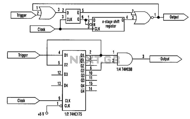
This approach utilizes a Hip-Hop, a shift register, and two gates (A). Before the one-shot pulse, the output of the NOR gate is 0. Consequently, the data input of the D-type flip-flop is equivalent to the trigger. When a...
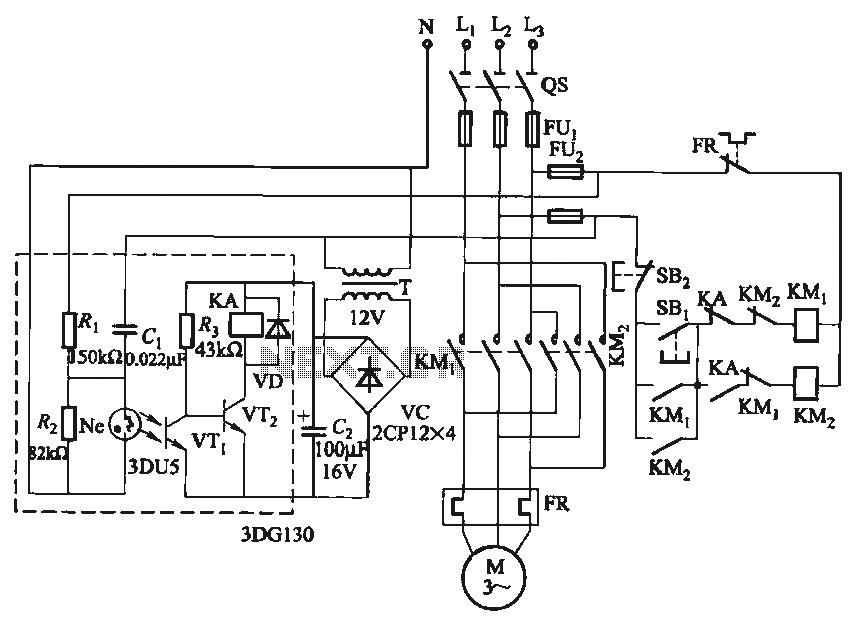
In certain applications, it is crucial to allow a motor to operate in only one specific direction, even when the power supply phase sequence is incorrect. This situation may arise due to external factors, such as incorrect wiring after...
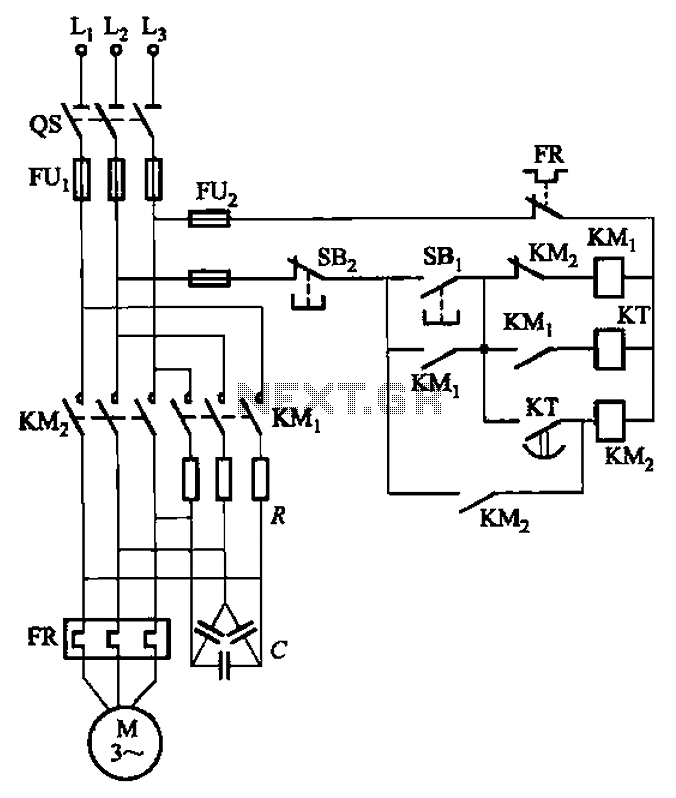
The circuit depicted in Figure 3-35 demonstrates a method for starting a motor that transitions to full voltage through a step-down switching process. This approach provides an uninterruptible power supply, effectively preventing issues related to switching currents that may...
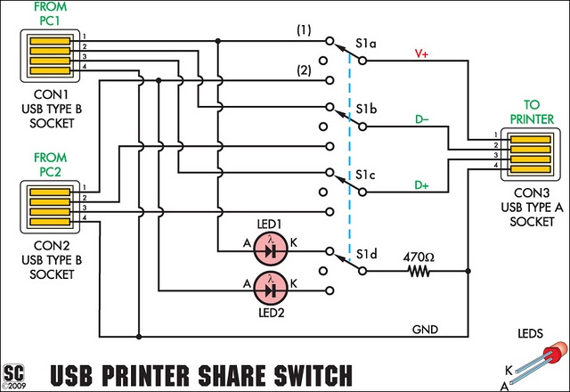
This simple device enables two computers to share a single USB printer or other USB devices, such as an external flash drive, memory card reader, or scanner. A rotary switch is used to select the PC that will be connected...
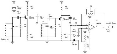
One type of metal detector is a beat frequency oscillator (BFO). The operation of metal detectors relies on changing the characteristics of the oscillator when it is near a metal object detected by the sensor. The detector functions based...
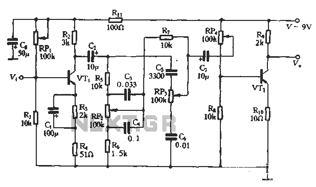
This article presents a diagram of an attenuated tone control circuit. The circuit primarily consists of transistors and RC networks as its components. The circuit operates in such a way that the shunt effect of capacitor C4 and resistor...
Warning: include(partials/cookie-banner.php): Failed to open stream: Permission denied in /var/www/html/nextgr/view-circuit.php on line 713
Warning: include(): Failed opening 'partials/cookie-banner.php' for inclusion (include_path='.:/usr/share/php') in /var/www/html/nextgr/view-circuit.php on line 713