
flash light electronic diagram
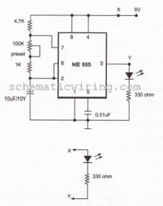
The circuit functions as a basic LED flasher using an astable multivibrator configuration, typically implemented with a 555 timer IC. The blinking frequency is determined by the resistor and capacitor values in the circuit. In this setup, capacitor C1 plays a crucial role in timing; its capacitance value directly influences the charge and discharge cycle, thereby adjusting the blinking interval.
The primary components of the circuit include:
- A 555 timer IC configured in astable mode.
- Resistors (R1 and R2) that set the timing intervals along with capacitor C1.
- A series of LEDs connected in parallel to the output of the 555 timer, with appropriate current-limiting resistors to prevent excessive current flow that could damage the LEDs.
To achieve the desired blink rate, the following formula can be utilized:
\[ f = \frac{1.44}{(R1 + 2R2) \times C1} \]
Where \( f \) is the frequency in hertz, \( R1 \) and \( R2 \) are the resistances in ohms, and \( C1 \) is the capacitance in farads. Adjusting the values of R1, R2, or C1 will modify the blink rate.
For applications requiring multiple LEDs, the circuit can accommodate additional units, ensuring that the total current does not exceed the output capacity of the 555 timer. It is advisable to use a transistor to drive larger numbers of LEDs, as the 555 timer can typically source or sink a maximum of 200 mA.
In summary, this circuit provides a simple and effective method for creating a blinking LED effect, with the flexibility to expand the number of LEDs used, making it suitable for various decorative or signaling applications.With this circuit, the LED blinks every half second. How long the blink time is, can be adjusted by adjusting the value of capacitor C1. Up to 18 additional LEDs can be attached to this circuit (36 LEDs total). 🔗 External reference
Related Circuits
The following describes the circuits of a minibus odometer, which integrates electronic and mechanical components to form a new type of instrument for measuring distance and speed. Pulse signals are generated by the locomotive speed detection system and transmitted...
The power failure light that I eventually designed and built is housed in the plastic case from a wall-mounted power transformer. I had accidentally destroyed the transformer by shorting its output, and had kept the plastic case for years,...
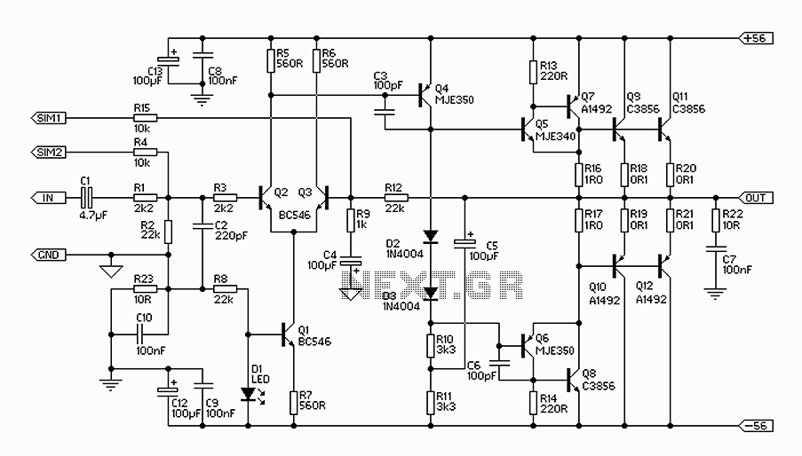
The 300W amplifier circuit presented is a conventional design. It includes connections for the internal SIM and incorporates filtering for RF protection (R1, C2). The input is facilitated through a 4.7µF bipolar capacitor, which offers substantial capacitance in a...
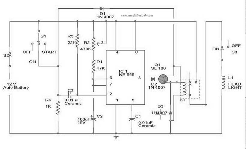
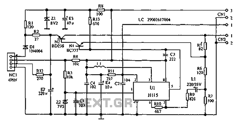
The circuit diagram for the automatic headlights turn-off circuit is presented here. This circuit can be installed in a car. The automatic headlights turn-off circuit is designed to enhance vehicle safety and convenience by ensuring that the headlights are automatically...
This circuit triggers an alarm when its LDR (Light Dependent Resistor) sensor is exposed to light from the sun or a lamp. A 555 astable multivibrator is utilized to generate a tone of approximately 1 kHz upon detecting light....
A DC capacitor tester circuit diagram utilizing a 555 timer is presented. The tester includes a pulse generator, a one-shot circuit, a DC amplifier, and a meter indication circuit. It is capable of measuring capacitors ranging from nanofarads (nF)...
Warning: include(partials/cookie-banner.php): Failed to open stream: Permission denied in /var/www/html/nextgr/view-circuit.php on line 713
Warning: include(): Failed opening 'partials/cookie-banner.php' for inclusion (include_path='.:/usr/share/php') in /var/www/html/nextgr/view-circuit.php on line 713