
XTal Tester
The described circuit utilizes a transistor (T1) in conjunction with a crystal oscillator (XTal) to generate an oscillating signal. Capacitors C1 and C2 serve as voltage dividers, ensuring that the oscillator receives the appropriate voltage levels for stable operation. The crystal oscillator operates effectively within the specified frequency range of 100 kHz to 30 MHz, provided that the crystal is functioning properly.
The output from the oscillator is then processed through capacitors C3 and C4, which are employed for filtering and smoothing the rectified output voltage. Diodes D1 and D2 are configured in a rectifying arrangement, converting the AC signal generated by the oscillator into a DC voltage suitable for powering subsequent components.
Transistor T2 acts as a switching device that is activated by the rectified output. When T2 is energized, it completes the circuit for the LED, allowing it to illuminate as an indicator of proper operation. This circuit is particularly useful for testing the functionality of various crystals within the specified frequency range, ensuring they can oscillate effectively when integrated into other electronic applications. The design emphasizes simplicity and efficiency, making it an ideal choice for basic testing and troubleshooting in electronic projects.T1 and XTal have formed an oscillator. C1 and C2 are voltage divider for oscillator. if the XTal is safe, the oscillator will work well and its output voltage will be rectified by C3, C4, D1 and D2, then T2 will run and LED will light. The circuit is suitable to test 100KHz - 30MHz Xtal. 🔗 External reference
Related Circuits
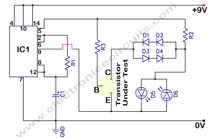
The circuit is a transistor tester schematic that indicates the condition of a transistor using two LEDs. It is designed to test a good NPN transistor. The transistor tester circuit operates by utilizing two light-emitting diodes (LEDs) to provide a...
I designed a simple sinewave generator based on a Analog Devices AD9832 chip. It will generate a sinewave from 0.005 to 12 MHz in 0.005 Hz steps. That's pretty good, and definitely good enough for me! But while waiting...
This circuit is a conventional Pierce-type oscillator that utilizes a JFET. It operates with fundamental mode crystals, offering decent performance and reliability when a low noise JFET is employed. The feedback is regulated by the capacitance of C1 from...
This project involves a straightforward soil moisture detection circuit that utilizes only four components and operates with a 3-volt battery. The circuit is designed to identify the presence of moisture in the soil of any plant and activate an...
This is basically a high gain amplifier with feedback that causes the LED to flash at a rate determined by the 10u and 330k resistor. Remove one of the transistors and insert the unknown transistor. When it is NPN...
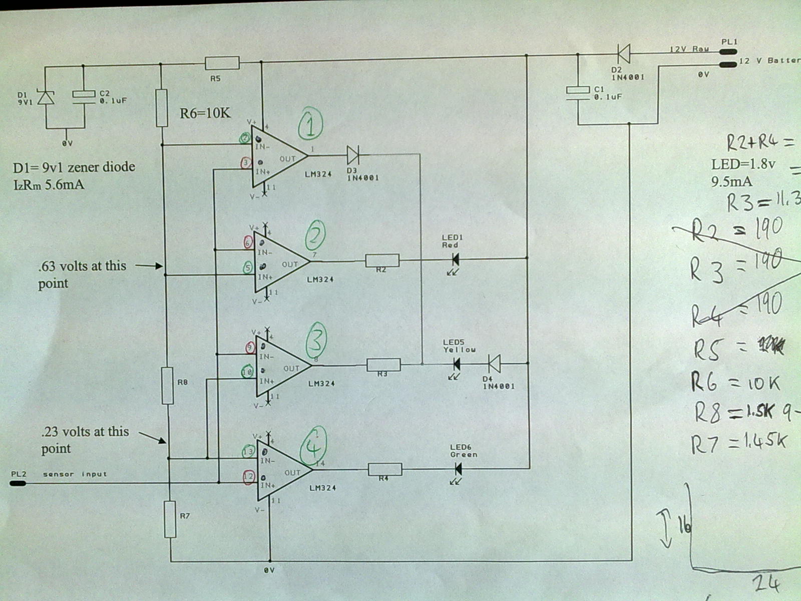
A 12V power supply is connected to the positive terminal, allowing current to flow through a protection diode and a capacitor that smooths the voltage. A zener resistor (R5) limits the current to the zener diode, which regulates the...
Warning: include(partials/cookie-banner.php): Failed to open stream: Permission denied in /var/www/html/nextgr/view-circuit.php on line 713
Warning: include(): Failed opening 'partials/cookie-banner.php' for inclusion (include_path='.:/usr/share/php') in /var/www/html/nextgr/view-circuit.php on line 713