
XTR108 circuit diagram of a three-wire RTD connection
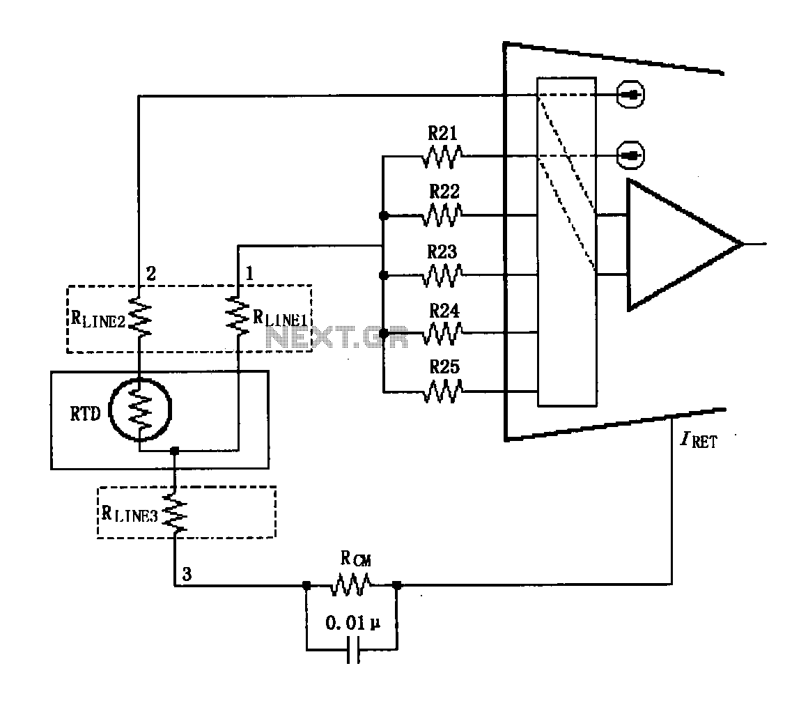
The XTR108 is a precision current-output temperature sensor interface designed to work with three-wire RTD (Resistance Temperature Detector) configurations. The three-wire setup is advantageous as it helps to compensate for lead resistance, a common source of error in temperature measurements. The circuit ensures that the effects of lead resistance are minimized, thereby enhancing measurement accuracy.
In the schematic, the connections labeled "1" and "2" denote the RTD leads, which connect to the XTR108. The lead resistance can introduce a voltage drop that may skew the temperature readings. The XTR108’s PGA plays a critical role in addressing this common mode voltage, effectively filtering out unwanted interference and improving the integrity of the signal.
Additionally, the circuit's design includes the capability to select from five different temperature ranges. This is accomplished through the use of resistors R21 to R25, which adjust the gain settings of the PGA. By altering these resistors, the circuit can be tailored to optimize performance for various temperature measurement applications, thus providing flexibility and precision in temperature sensing.
Overall, the design of the XTR108 three-wire RTD connection circuit emphasizes accuracy, flexibility, and noise reduction, making it suitable for a wide range of temperature monitoring applications.Shown for the XTR108 three-wire RTD connection circuit. Sensor connection RTD lead resistance may introduce errors. Using the figure and 2 connection, if "1" and "2" to XTR108 lead length as the lead resistance, as the size and direction of the interference introduced too. This interference belong to the common mode voltage, common-mode voltage can be suppressed by XTR108 the PGA.
The circuit has five selectable temperature range, i.e., by selecting R21 ~ R25 to select five different minimum temperature characteristics.
Related Circuits
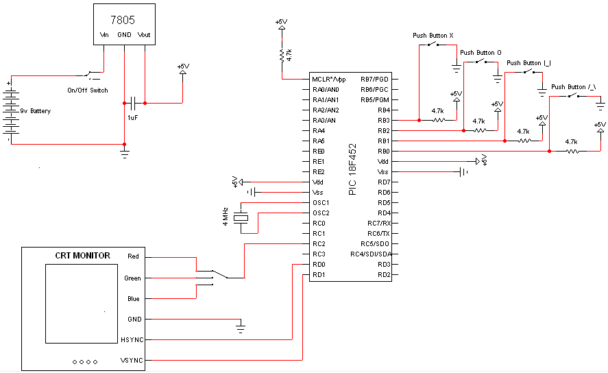
Very few electronic components are required for this project, as the PIC Microcontroller serves as the primary processing unit. The essential components include buttons, switches, and a power circuit, which are straightforward forms of input/output, facilitating an easier understanding...

This magic lamp appears to be an ordinary frosted light bulb with a rather unusual characteristic. Whenever a finger touches the base threads and center contact, the lamp magically lights up without wires. It creates a compelling illusion if...

The circuit utilizes a Pt100 type resistance temperature detector (RTD). It operates within a temperature range of 100 to 600 °C, where the XTR105 outputs a current of 4 to 20 mA, and the RCV420 provides an output voltage...
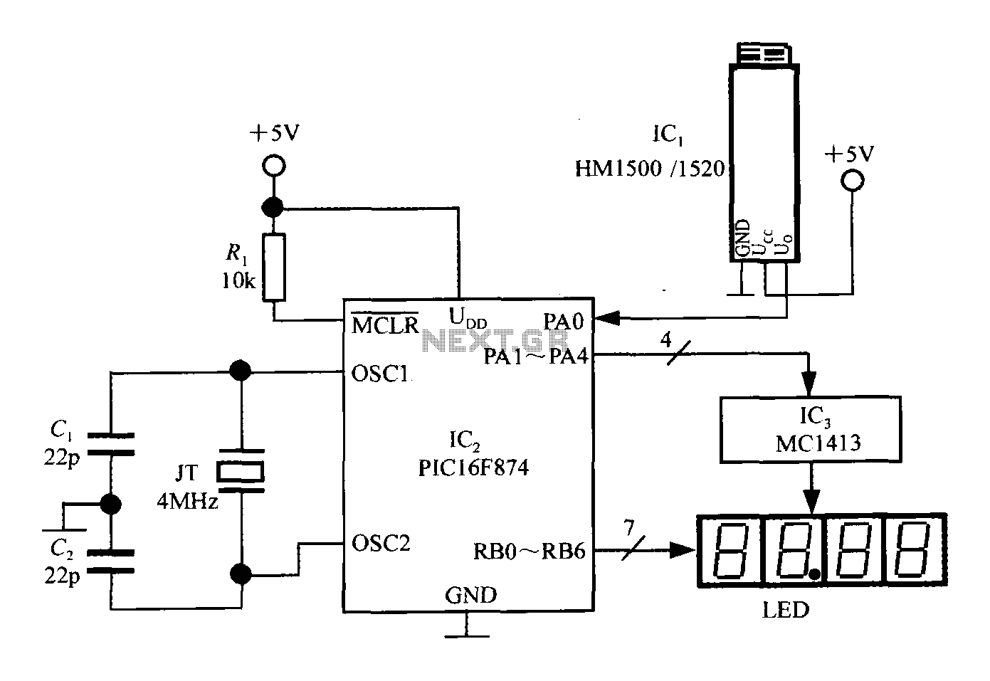
An intelligent humidity meter circuit utilizing the HM1500/1520 humidity sensor and a microcontroller configuration. The circuit operates on a +5V power supply and incorporates four common cathode LED digital displays. It employs three integrated circuits: IC1 is the HM1500/1520...
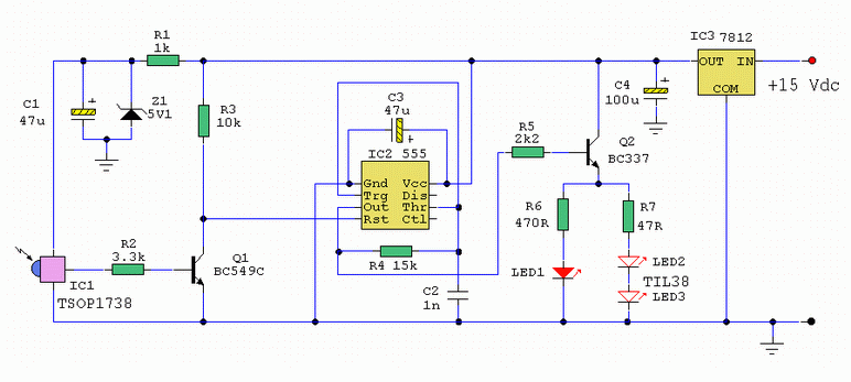
An infrared wired repeater circuit is designed to control appliances from a remote location. Parts List: R1: 1k Resistor (1), R2: 3.3k Resistor (1), R3: 10k Resistor (1). The infrared wired repeater circuit serves as an interface for controlling various...

A very useful talk-over circuit that can be utilized in radio stations, clubs, or any location where speaking over music is desired without the need for adjusting a potentiometer. The talk-over circuit is designed to automatically reduce the volume of...