
Yaesu FT-101 HF Transceiver
The 6JS6C tube serves as a pivotal component in the FT-101E transceiver, facilitating RF amplification within the specified frequency range. Its design as a sweep tube allows it to handle the demands of television deflection applications, while its performance characteristics extend its utility to amateur radio applications. The need for careful replacement and modification of associated components, such as the neutralization circuit, underscores the importance of precision in maintaining the integrity of the transceiver's operation.
The modification process requires the removal of the existing 100 pF capacitor and substitution with a 10 pF capacitor, which must be rated for high voltage to withstand the operational conditions within the transceiver. This adjustment is critical to ensure proper neutralization of the circuit, which is essential for minimizing unwanted oscillations and ensuring efficient signal transmission. The orientation and lead length of the capacitors must be preserved to maintain the circuit's performance characteristics.
During the tuning process, operators must exercise caution due to the presence of high voltage in the circuit. The use of non-metallic tools is imperative to prevent electrical shorts or accidental discharges. Following the neutralization procedure, the bias settings must be carefully calibrated to ensure optimal performance of the 6JS6C tubes, thereby prolonging their lifespan and maintaining the integrity of the transceiver.
In summary, the FT-101E transceiver's reliance on the 6JS6C tube and the associated neutralization modifications highlight the intricate relationship between component selection, circuit design, and operational efficacy in high-frequency amateur radio applications. Regular maintenance, including retuning and adherence to safety protocols, is essential for sustained performance and reliability of the transceiver.The 6JS6C tube is a TV Deflection Tube, or "Sweep Tube". Although not meant for transmitting, it exhibits sufficient performance for RF operation through 30 MHz. Each tube can dissipate 30 watts of plate power. The base is a 12-pin socket. There will come a time when the finals in your FT101E will need replacing. The FT-101 transceivers were origi nally equipped with 6JS6C tubes manufactured by NEC and Toshiba. Other manufacturers tube properties are slightly different from the original 6JS6C tubes. Therefore, a simple modification to the neutralization circuit must be made to the final section of the transceiver. The modification consists of replacing the fixed value 100 pf 1000 VDC mica capacitor with a 10 pf 1000 VDC mica capacitor.
This capacitor, C125, is in series with the 10 pf variable neutralizing capacitor off of the plate circuit. If this modification has not already been completed on your rig, be sure to use a mica or silver mica of at least 1000 VDC.
Do not substitute a different type because the heat in the final compartment will change the value, and your tubes will fail prematurely. Also, be very careful to keep all leads short and in exactly the same orientation as the original capacitor.
Before re-neutralizing, open the variable neutralizing capacitor all the way to minimum engagement and follow the neutralizing instructions in the manual. While dipping the PLATE, remember to adjust the neutralizing capacitor for equal value meter reading "dips" (Ic meter position) on both sides of the peak when tuning the PLATE control.
WARNING! You are tuning a capacitor in the High Voltage compartment, +600 Volts are present! Always use non-metallic tuning tools. After neutralization, reset the bias to 60ma with CARRIER and MIC settings at minimum. QST- The following performance data is provided by the American Radio Relay League (ARRL) and their publication QST. A full copy of this table was found on the Technical Information Service section on the ARRL web page.
The table depicted over 60 radios and their performance data. I have shown only the Yaesu radios from the 1970`s that apply to this web page. QST Reviews of Amateur HF Transceivers QST | Xmtr | Rcvr Rig Review| Harm. Spurs IMD | Min Sig BlkRng IMD DR 3rdO Icpt Issue | dBpep dBpep dBpep| dBm dB dB dBm - Yaesu: FT-101B 02/74 FT-101E 09/76 -34 -141 108 81 FT-101Z 12/79 -45 -38 -139 112 78 -22 FT-301 10/77 -55 -68 -40 -133 100 75 FT-901 11/78 -46 -57 -38 -137 114 85 If you have ever purchased a FT-101 transceiver without the Instruction Manual, you know it can be very intimidating to operate until you perform the tune-up process a time or two. Without `tuning up` your transmitted and received signals really suffer AND could actually damage the tubes in the power amplifier.
I always suggest that you download the Instruction Manual for any FT-101 radio or accessory you own. Even older radios have web pages that can provide you copies at very reasonable rates. An Instruction Manual was made for each and every FT-101 radio and accessory. These are free across the Internet. Even the FT-101 Service Manual is available (32MB PDF). See the FT-101 Repair Facilities section on this page for the link. No excuses! The FT-101 series is a very mechanical radio. The size, selection, and operation of this rig allow for very high-Q circuit tuning. It is a very strong point with the FT-101 series. As with any high-Q circuit, it must be continuously tuned for maximum efficiency. Once learned, it takes only a few seconds to perform. You should re-tune anytime you change bands, change antennas, or move a significant distance (in frequency) from where you last tuned up. This may be as large as 200 kHz on the 10 meter band (10-15 turns of the VFO dial) or as little as 15 kHz on the 160 meter band (one turn of the VFO dial).
Before you begin, you should allow the rig to warm up (with the heaters on) for at least 15 minutes. This 🔗 External reference
Related Circuits
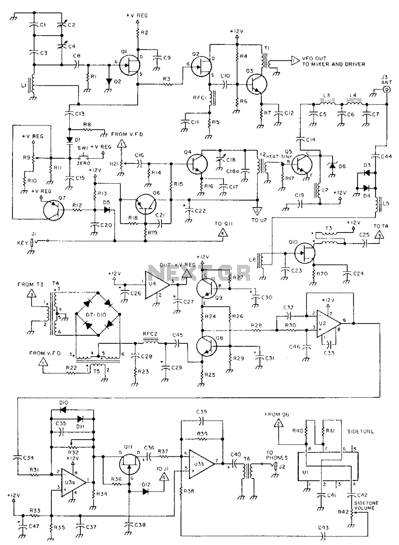
This is a 3-W, single-circuit board, VFO-controlled CW transceiver for 40 or 30 meters, featuring a direct-conversion receiver with audio filtering, Receiver Incremental Tuning (RIT), and speaker-level audio volume. The transmit frequency is generated by Q1 and its associated...
1. Full 5 watt output using a power MOSFET final that is resistant to high SWR and thermal runaway. This final is very efficient and runs much cooler than traditional bipolar designs. 2. Highly sensitive and selective superhetrodyne receiver...
The MLX90224 series consists of dual Hall effect latches. It features two Hall effect latch functions with typical thresholds of +/- 2.0 mT. Each latch utilizes a switched silicon Hall plate for magnetic flux detection. The BOP and BRP...
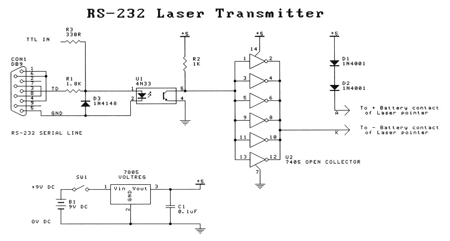
This project is intended for entry-level laser experimenters. The circuit enables communication between two computers with serial (RS-232) capabilities over a distance of 200 meters using a laser beam. A low-cost transmitter-only circuit is also provided for one-way communication...
The RF signal is divided into two signals that are shifted 90 degrees out of phase (one at plus 45 degrees and one at minus 45 degrees). Both signals are then mixed to audio frequencies. The two audio signals...

The 7MHz CW transceiver is constructed using the MC3362P integrated circuit, originally intended for a 10MHz band transceiver. Due to concerns regarding unexpected neighboring spurious signals, the frequency was altered to 7MHz, leading to the completion of the transceiver....