
Z80-Family Official Support Page
The Z80 microprocessor family, originally developed by Zilog in the late 1970s, has become a foundational element in numerous computing applications. The architecture is characterized by its 8-bit data bus and 16-bit address bus, allowing for a maximum addressable memory space of 64KB. The Z80's instruction set is rich, supporting a variety of addressing modes, which enhances programming flexibility.
When designing a circuit that incorporates a Z80 microprocessor, several key components must be considered. The microprocessor typically requires a stable power supply, often 5 volts, along with decoupling capacitors to filter out noise and ensure stable operation.
The microprocessor interfaces with memory through address and data buses. Static RAM (SRAM) or dynamic RAM (DRAM) can be used for memory, depending on the application requirements. Additionally, the Z80 can be interfaced with various input/output devices through its I/O ports. For example, a parallel interface can be created using 74HCxx series logic gates to connect peripherals.
Clock signals are crucial for the operation of the Z80. A crystal oscillator or a clock generator circuit can be used to provide the necessary timing signals. The typical clock frequency for Z80 operation ranges from 2.5 MHz to 6 MHz, depending on the specific model and application.
In terms of programming, the Z80 can be programmed in assembly language, which allows for direct control of hardware resources. Development environments may include emulators and assemblers that facilitate code writing and debugging.
Overall, when embarking on a Z80-based project, it is essential to carefully plan the circuit design, taking into account the availability of components, compatibility, and the specific requirements of the intended application. This thorough approach will ensure a successful implementation of the Z80 microprocessor in any electronic project.The purpose of this page and its sub pages about members of Z80 family (and close relatives) is to collect and share information and good ideas. I know there are lots of people out there, who have developed some good utilities and hardware solutions.
Now we all can share this infomation. Some of the links here are no more online and some are not y et correct: they are marked with a sequence; in case you know the appropriate URL: I`m ready for an update. Be aware of the fact that many products mentioned in this series of Z80 related documents are nowadays out of production: if you want to start a project, don`t forget to check where to get the parts from, and what the conditions are.
🔗 External reference
Related Circuits
This laser is constructed on a polystyrene sheet. An aluminum foil layer acts as a ground plate (-), which is important for preionization. After that, the dielectric is placed on it, leaving 1 cm from each border of the...
The GPS interface can be fed in 2 ways: with a stabilized 5V supply or with a 10 to 25V unregulated DC supply. In both cases, the power is fed into the RJ45 connector on point 8. Pin 7...
The circuit operates but exhibits instability, particularly with temperature variations. For example, upon powering it on and tuning it, switching it off and on again affects its performance. The control voltage (CV) output is essential for the theremin/controller circuit....
Every inexpensive energy-saving lamp contains a self-resonant voltage inverter designed for low-power operation, typically up to a few watts. It raises the question of why not scale up this concept and replace the resonance circuit used to generate the...
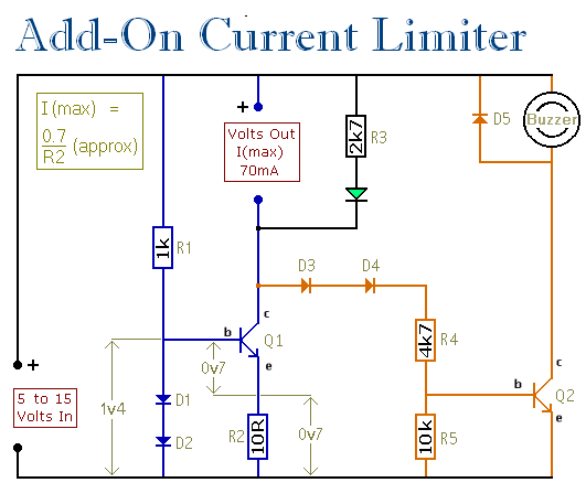
This circuit establishes a maximum limit on the current available from the output terminals by controlling the maximum current that can flow through Q1. The output terminals are in series with Q1, meaning that limiting the current through Q1...
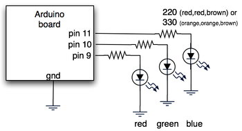
The hardware consists of an Arduino board connected via USB to a laptop, which recognizes the Arduino as a serial device. Three LEDs (red, green, blue) are mounted directly on the Arduino board using a prototyping shield. The schematic...