
Zero-crossing detector

As the input signal increases (greater than +10 mV), the output of comparator A will be low while comparator B will output high. Conversely, when the input signal decreases (less than -10 mV), the outputs will reverse. The combined outputs will remain low in both scenarios. However, when the input signal is within the threshold range (±10 mV around the zero crossover), both comparators will output high. To increase hysteresis, the ±10 mV window can be widened by adjusting the reference voltages.
The zero-crossing detector circuit is a critical component in various electronic applications, particularly in phase-locked loops and signal conditioning systems. The dual LM393 comparator configuration provides a robust method to detect the point at which an AC signal crosses zero volts, facilitating reliable switching actions in digital circuits. The use of hysteresis prevents false triggering caused by noise or fluctuations around the zero-crossing point, enhancing the stability of the output signal.
In practical applications, the circuit can be integrated into microcontroller systems or digital signal processing (DSP) environments where precise timing and synchronization with AC signals are necessary. The TTL-compatible output ensures seamless interfacing with standard digital logic circuits, making this zero-crossing detector versatile for both low-power and high-speed applications. The design can be further optimized by selecting appropriate resistor and capacitor values to tailor the response time and hysteresis characteristics to specific requirements.This zero-crossing detector uses a dual LM393 comparator, and easily controls hysteresis by the reference levels which are set on the comparator inputs. The circuit illustrated is powered by +10-V power supplies. The input signal can be an ac signal level up to + 8 V. The output will be a positive going pulse of about 4*4 V at the zero-crossover point. These parameters are compatible with TTL logic levels. The input signal is simultaneously applied to the non-inverting input of comparator A and the inverting input of comparator B.
The inverting input of comparator A has a +10 mV reference with respect to ground, while the non-inverting input of comparator has a -10 mV reference with respect to ground. As the input signal swings positive (greater than +10 mV), the output of comparator "A" will be low while comparator "B" will have a high output. When the input signal swings negative (less than -10 mV), the reverse is true. The result of the combined outputs will be low in either case. On the other hand, when the input signal is between the threshold points (±10 mV around zero crossover), the output of both comparators will be high.
If more hysteresis is needed, the ± 10 mV window may be made wider by increasing the reference voltages.
Related Circuits
The basic operation of the monitor connected to the circuit is to detect objects (obstacles) at distances ranging from a few millimeters to several centimeters. This type of circuit is utilized in various industries and hospitals. The position sensor...
This is a basic Cadmium Sulfide (CdS) photocell detector circuit. In this circuit, when light falling on the photocell (PC1) is blocked, its resistance increases, causing the voltage across PC1 to rise. When the voltage exceeds half of the...
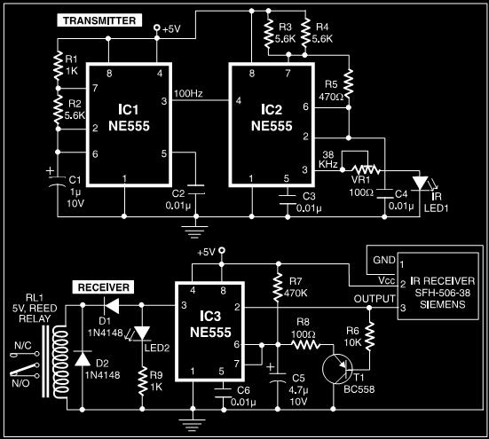
This post discusses a proximity detector circuit primarily utilizing the NE555 integrated circuit (IC). The circuit is designed for burglar alarms based on beam interruption, with the advantage that the transmitter and receiver are contained within the same enclosure,...
The following circuit illustrates a Light Barrier Sensor Detector Circuit Diagram. Features include a single transistor, an adjustable potentiometer, and a 6V power supply. The Light Barrier Sensor Detector Circuit is designed to detect the presence of an object by...
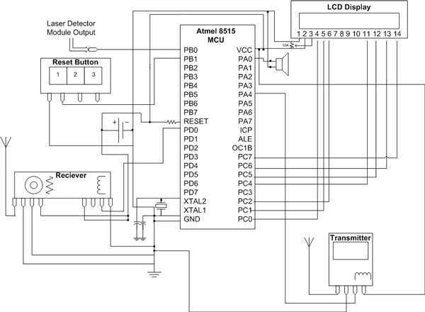
The hardware for this project had three main components: laser gun assembly, detector unit, control pad. The detector unit's function was to simply detect a laser pulse over a small area sent by the laser driver circuit on the...
The bat ultrasounds are picked up by the microphone SPKR1 and go through two stages of amplification at Q1 and Q2. Separately, a tunable (R12) single frequency is produced by the LM567 oscillator U1. The LM567 is a tone...