
Dual flashing string circuit 2

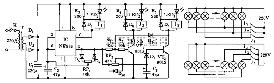
The thyristor-controlled unidirectional flashing light string controller is designed to manage the operation of two separate light strings, E1 and E2, in an alternating manner. The core of the circuit relies on the switching capabilities of thyristors VT3 and VF4, which are triggered by the activation states of transistors VT1 and VT2. The multi-oscillator circuit provides the necessary timing signals to ensure that VT1 and VT2 operate in a complementary fashion, allowing one to turn off while the other turns on.
The resistors R1 and R2 serve as current limiting and biasing components, ensuring that the thyristors receive the appropriate gate trigger currents. The use of diodes VT1 and VT2 helps prevent backflow of current, ensuring that each thyristor operates effectively within its specified parameters. The LED indicators I1 and I2 not only provide visual feedback on the operational status of the light strings but also serve as a diagnostic tool for troubleshooting the circuit.
The multivibrator section of the circuit is crucial for establishing the flashing frequency of the light strings. By adjusting the resistance in the feedback loop, the frequency of the oscillation can be modified, allowing for customization of the flashing pattern. The choice of components, including the use of standard thyristors and polypropylene capacitors, ensures reliability and ease of sourcing, making the circuit suitable for various applications in decorative lighting or signaling systems.
Overall, this thyristor-controlled flashing light circuit exemplifies an efficient and effective design for managing alternating light displays, utilizing basic electronic components to achieve a visually appealing result.As is the use of thyristor controlled unidirectional flashing lights string controller, diodes VTI, VT2 connected to a multi-I are from Che oscillator, after power, VT1, VI12 t ake turns alternately turned on and off. When VT1 is turned off when VT2 DC power supply on by R;, IFDl single injection of the thyristor VT3 door, so vn opened, El string lights lit; if VT1 end, when VT2 guide slovenly, when the light-emitting tube I. EDl off, VT3 fail to trigger current shutdown, E1 put out in particular. While DC power supply by R, I: D2 injection of one-way thyristor VF4 f J pole, so v D 4 E2 open string lights lit, so the labyrinth light strings El and F: 2 alternately flashing light and flame.
LED tube plate I. F: r) l and LFD2 play indication, representing J bright fire and light string {: l, F2 synchronous deep change section RP old white excited multivibrator oscillation frequency, it. Section can split half flashing lights. AC frequency comb. VT3, VT4 cho MCRI .- S-type and other small plastic single product BJ thyristor .f require (: 1-1H 400V polypropylene capacitors five other devices without special requirements.
Related Circuits
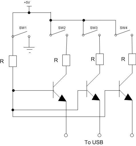
Four switches will be connected to a USB joystick board. The USB board has +5V and ground connections and emulates a button press. The circuit involves interfacing four mechanical switches with a USB joystick interface. The USB joystick board typically...
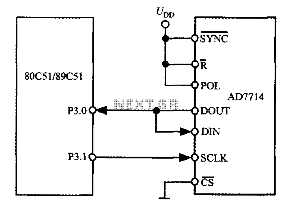
The 3-wire interface to the AD7714 can be utilized with various microcontrollers, including microcontrollers and microprocessors. This 3-wire serial interface is particularly suitable for isolation systems, allowing the use of optical couplers. The interface circuit between the AD7714 and...

There are important considerations when using additional memory, but it is certainly feasible. The MP3 player project utilizes 32 megabytes of memory. However, using more memory necessitates careful planning. The key factor is that the 8051 processor has a...
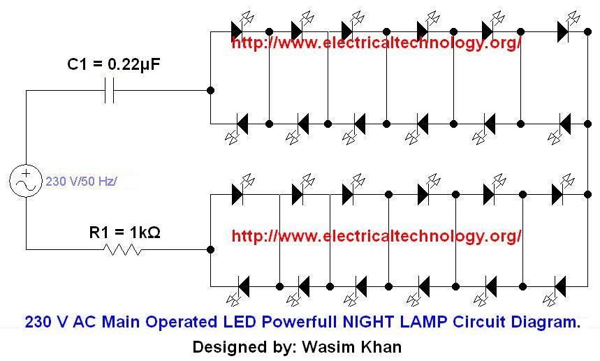
If you plan to use this circuit with a 110V 60Hz supply instead of a 230V 50Hz supply, or if you intend to modify this circuit, please refer to the section titled "Common Questions about this Circuit" found below...
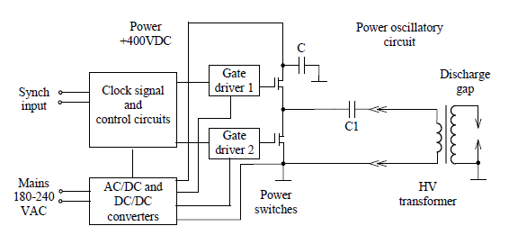
Simulate the electric field within a gas-filled discharge gap generated by a radio frequency voltage generator. The circuit, provided by the experimenters at a distance, is depicted in the accompanying image. The numerical values are as follows: C1 =...
The controller features a buck rectifier circuit utilizing a 555 multivibrator, designed for controlling approximately 220V, 5W low-power parallel lights or 6 to 12V small bulb series. The 555 timer, along with components D3, D4, RP1, and C2, forms...