
Autoranging Circuit

Autoranging is a technique employed in electronic measurement systems to automatically adjust the range of an analog-to-digital converter (ADC) based on the input signal level. This method enhances the ADC's ability to accurately measure a wider range of input voltages without requiring manual range adjustments. In a typical autoranging setup, the ADC is connected to a multiplexed input system that can switch between different resistor divider configurations or gain settings.
The circuit generally consists of an ADC, a multiplexer, and a set of resistors or operational amplifiers (op-amps) configured to provide various gain levels. The multiplexer selects the appropriate gain setting based on the detected input voltage. A feedback mechanism is often included, which continuously monitors the ADC output and adjusts the gain accordingly to ensure optimal measurement accuracy.
For example, if the input voltage exceeds a predefined threshold, the system can switch to a lower gain setting or a higher resistor divider ratio to bring the input voltage within the ADC's operational range. Conversely, if the input voltage is low, the system can switch to a higher gain setting to maximize resolution.
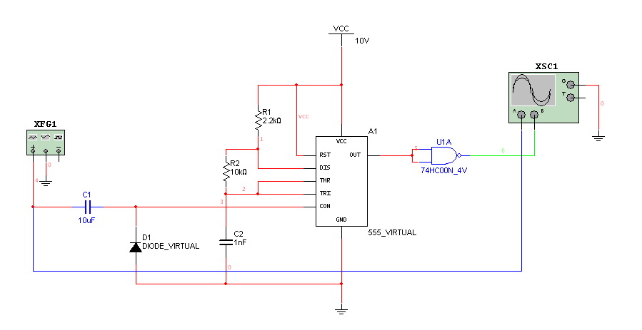
The implementation of autoranging in a multiplexed input system allows for efficient use of ADC resources, enabling the measurement of signals that vary significantly in amplitude without sacrificing precision or requiring user intervention. This capability is particularly beneficial in applications such as data acquisition systems, sensor interfaces, and instrumentation where signal levels can fluctuate widely.To extend the measurement range of an available ADC(analog to digital conveter) we can use this autoranging. If it implemented on multiplexed input, this.. 🔗 External reference
Related Circuits
Hello everyone. I need some help. I have constructed a PWM and PPM circuit. The output is functioning smoothly, but I am experiencing some problems and I am not very experienced. The PWM (Pulse Width Modulation) and PPM (Pulse Position...
Make the following connections: GND (pin 8) to ground, Vcc (pin 16) to 5V, OE (pin 13) to ground, MR (pin 10) to 5V. This setup makes all of the output pins active and addressable at all times. The...
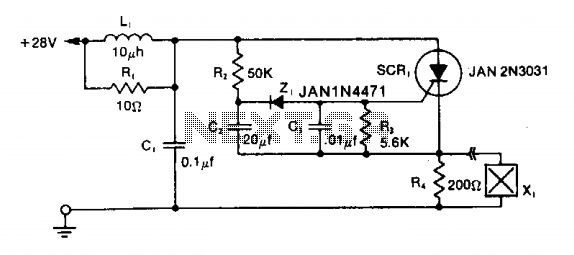
The LRC input network limits the anode dv/dt to a safe value below 30 V/μs. Rl provides critical damping to prevent voltage overshoot. While a simple RC filter section could be used, the high current required by the squib...
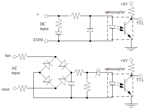
PLC input cards typically do not provide power, necessitating an external power supply for inputs and sensors. An example of an input card and a ladder logic diagram illustrates how to connect an AC input card. The PLC inputs...
This circuitry provides a magnification of 1,200,000 times, with a bandwidth ranging from 0.5 to 14 MHz. The input impedance is 700 ohms, while the output impedance is 35 ohms when measured at 5 MHz. The output noise level...
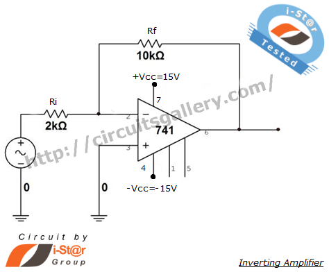
An inverting amplifier is one of the most widely used operational amplifier circuits. The output adjusts in a manner that counteracts changes caused by the input, thereby preventing saturation and ensuring stability. By connecting a resistor from the output...