
Fans can light three-gear speed control circuit

The circuit operates in two modes: manual and automatic. In manual mode, the user can control the fan's operation directly through button SB. This allows for immediate adjustment of the fan speed according to user preference. In automatic mode, the circuit uses a phototransistor, which senses ambient light levels. When a flashlight beam is directed at phototransistor VTj, it triggers the circuit to engage the fan, which then cycles through its speed settings in a predetermined sequence.
The CMOS hex inverter Icl is crucial for processing signals within the circuit. It takes the output from the phototransistor and inverts it, ensuring that the subsequent stages of the circuit receive the correct logic levels. The resistor-capacitor (RC) network connected to the inverter serves as a timing mechanism, generating clock pulses that dictate the timing of the fan's speed adjustments.
The integrated circuit Icz operates as a decimal counter and timing decoder, translating the clock pulses into control signals for the transistors VTz to VT4. These transistors act as switches, allowing current to flow to the TRIACs Vl to V3, which regulate the power delivered to the fan motor. The TRIACs are essential for controlling the fan speed by adjusting the power delivered based on the control signals from the integrated circuit.
In summary, this circuit design effectively combines manual and automatic control of a fan, utilizing light detection to enhance user convenience while maintaining precise control over fan speeds through a well-structured electronic design. The integration of CMOS technology, timing circuits, and power control devices exemplifies a sophisticated approach to fan speed regulation in various lighting conditions. Circuit shown in Figure 3-5. It can be manual (button SB) and light control (phototransistor VTj). When the light of a flashlight quasi VTi, fans will turn on the operation, an d sub slow, medium, fast three times a block is automatically adjusted. A CMOS hex inverter Icl (door F2-F4) and resistance, capacitance circuit clock pulse generator. By an integrated circuit Icz decimal counting/timing decoder transistor VTz ~ VT4, TRIAC Vl-V3 wind speed fan and other components (gear) switch circuit.
Related Circuits
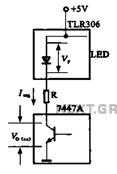
The circuit depicted is a large high-brightness LED driver designed to provide sufficient drive current, utilizing integrated circuits such as the 7447A or 74247. The digital display tube consists of eight light-emitting diodes, with seven dedicated to the digital...
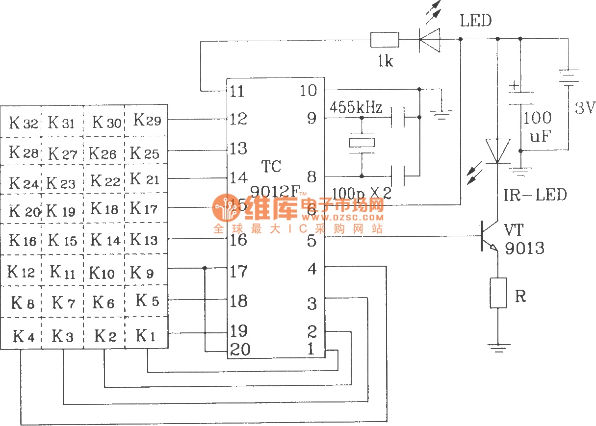
The TC9012 is a specialized off-screen remote control code transmitter. It incorporates an oscillator, divider timing generator, system code latch, data storage, key scan input, key scan output, and carrier control and output units. The internal 8-bit system code...
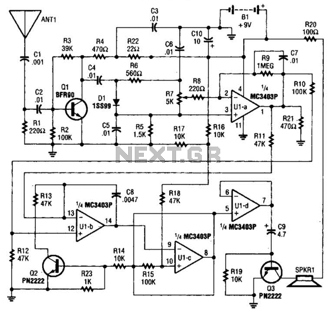
The circuit is constructed around a single integrated circuit (U1), specifically an MC3403P quad op-amp, three transistors (Q1-Q3), and several supporting components. It receives its input from the antenna (ANT1). The signal is processed through a high-pass filter composed...
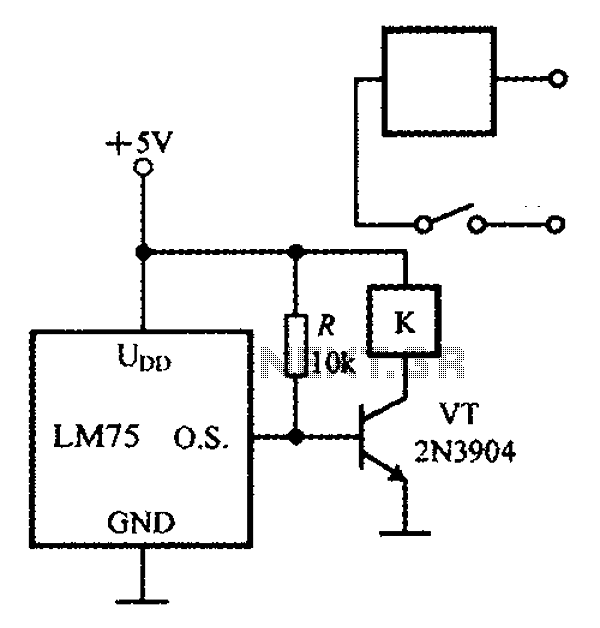
The circuit features simple smart temperature sensors utilizing an I2C bus interface, designed as a thermostat controller circuit. It employs the LM75 temperature sensor connected to a 2N3904 transistor, which drives a relay coil. The relay operates based on...
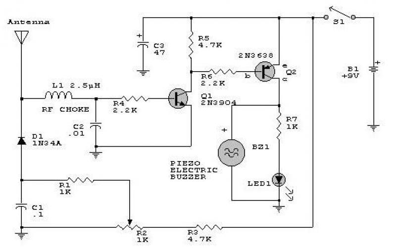
This circuit responds to RF signals below the standard broadcast band up to over 500 MHz and provides both visual and audible indications when an RF signal is detected. By adjusting the bias of diode D2 with the R2...
Simple two-wire remote monitoring unit with a three-LED level display, powered by a 9V battery. The entire project was developed at the request of a friend. The remote monitoring unit is designed to provide a straightforward solution for level indication...