
CXA1191 AM/FM Reciever

The described radio circuit comprises several key components that facilitate the reception and processing of both AM and FM signals. The central element is the radio integrated circuit (IC), which is strategically positioned in the middle of the board. Above the IC, a blue ceramic filter designed for 10.7 MHz is employed to filter FM signals, ensuring that only the desired frequency components are passed for further processing.
At the top of the assembly, a yellow AM intermediate frequency (IF) filter tuned to 455 kHz is present. This filter can be utilized as a quadcoil due to its inductive-capacitive (LC) characteristics. The design includes two additional cans: a red can that houses the AM oscillator, operating within the 0-2 MHz range, and a pink can that serves as a quadcoil for FM demodulation, which is also tuned to 10.7 MHz.
Adjacent to the IC, two tuning elements are located. The upper component functions as a volume control, while the lower component is a variable capacitor, comprising four tunable capacitors within a single housing. Typically, two capacitors are rated between 5-30 pF, and the other two range from 10-130 pF, allowing for precise tuning adjustments.
An aircoil is positioned a few centimeters above the red can, linked to the antenna and functioning as an antenna filter to optimize signal reception. Notably, this radio design lacks a ceramic filter for 455 kHz, which is often present in higher-quality designs. In the schematic, the absence of this filter may be represented in series with the yellow can, but it is omitted in this lower-quality implementation.
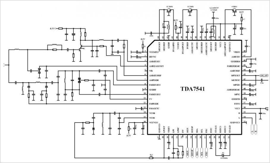
The mixer output is routed to pin 15 of the IC, with the FM signal subsequently passing through the 10.7 MHz ceramic filter and the 455 kHz AM signal filter. The primary winding of the filter connects pins 1 and 3, with a capacitor also linked to these pins. A tap point exists from the primary winding to pin 2; however, the schematic may inaccurately depict the winding as connecting pins 2 and 3. Despite this, the filter's functionality remains intact. It is important to note that the impedance seen by the filter can vary depending on whether pin 1 or pin 2 is utilized, with pin 3 consistently being used as a reference point.
For applications requiring the filter to be used as a quad coil, it is advisable to connect pins 1 and 3. The filter also features a secondary winding connected between pins 4 and 5. The output from this filter is fed back into the IC at pin 17, while the FM signal is directed to pin 18, completing the signal processing pathway. This schematic effectively outlines the fundamental components and their interconnections, illustrating the operational principles of the radio circuit.The radio IC is in the middle of the board. Above the IC you will find a ceramic filter (10.7MHz) for the FM part. This filter is blue. At the top you will find the yellow AM IF filter. This filter is a 455kHz tuned filter. The slug is in yellow color. You can use this filter as a quadcoil because it is a LC unit tuned to 455kHz. There is two more cans. One is red, this is the AM oscillator (0-2MHz). The can with pink color is a quadcoil for the FM demodulation. This can is a LC unit tuned to 10.7MHz. At the right side you will find 2 tuning things. The one at the top is the volum control and the one at the bottom is a variable capacitor. Actually it is four tunable capacitor in one house. Most often there are two in the range 5-30pF and two with the range 10-130pF. At the right side of the IC, a few cm above the red can you can find a aircoil. This coil is connected to the antenna and acts as an antenna filter. The rest is for the audio part. One thing you should notic is that this radio doesn't have a ceramic filter for 455kHz . In the schematic you might find this filter in serie with the yellow can, but this radio is of lower quality and the have left it out. If we take a closer look at the schematic you will be able to identify the components. Everything inside the red box is actually inside the can with yellow slug. The product from the mixer comes out at pin15 and the FM signal passes through the 10.7MHz ceramic filter and the 455kHz AM signal filters in the can.The primary winding in the filter is actually from pin1 to pin3 and the cap is also connected to pin1 and pin3 (fig at right).
There is a tap point from the primary winding to pin2. In this schematic they have drawn it to look like the winding is from pin2 to pin3 wich is not true, but this is just details because the filter will work the same, the only thing is that the impedance into the filter is different if you use pin1 or pin2. Pin3 is always used. If you are going to use this filter as a quad coil I recommend you to use pin 1 and pin 3. The filter has a secondary winding from pin4 and pin5. The output from the filter goes back into the IC at pin 17 and the FM goes into pin 18. 🔗 External reference
Related Circuits
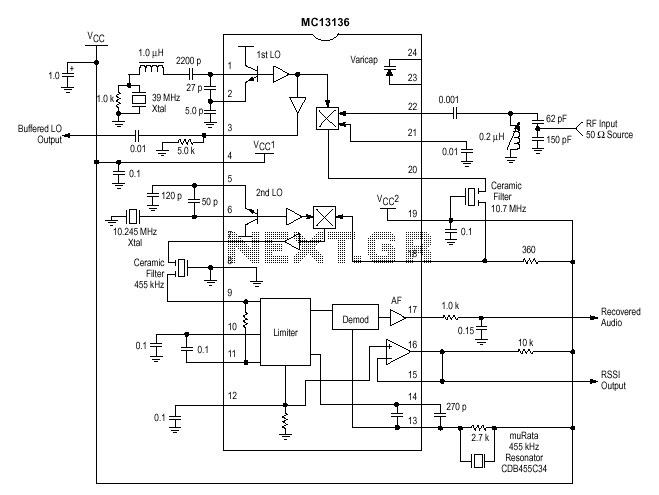
One of the circuits used in projects is the MC13135/MC13136. It is the second generation of single-chip, dual-conversion FM communication receivers developed by Motorola. Major improvements in signal handling, RSSI, and first oscillator operation have been made. At pin...
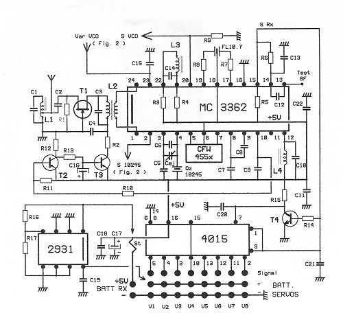
This receptor is born of our annoyance against the irritating problem of Quartz: With the RX21, completed research of cut crystal for your personal rating, you have with him, access to ALL band frequencies, in steps of 5 kHz!...
This is the complete circuit of the modern homodyne receiver. This receiver can receive AM, CW, and SSB transmissions. The modern homodyne receiver is a sophisticated device designed to process various types of radio frequency signals, specifically Amplitude Modulated (AM),...
The basic MK484 (Replacement for the ZN414) connected in its minimum configuration as a radio receiver for the A.M. Broadcast band and the upper half of the United States' FCC Part 15 Lowfer (1600-1750 meter) band. It's a circuit...
The TDA8340Q and TDA8341Q are integrated intermediate frequency (IF) amplifier and demodulator circuits designed for color and black-and-white television receivers. The TDA8340Q is intended for use with NPN tuners, while the TDA8341Q is suitable for PNP tuners. Both components...

This circuit is designed to generate audio musical notes that can be heard from a distance of up to 10 meters. The circuit consists of two main components: an infrared (IR) music transmitter and an IR music receiver. The...