
1 Hour Timer

No description available.
Related Circuits
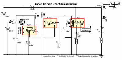
Timer garage door circuit schematic diagram, printed circuit board. The timer garage door circuit is designed to automate the opening and closing of a garage door based on a predetermined time interval. The schematic diagram illustrates the layout and connections...
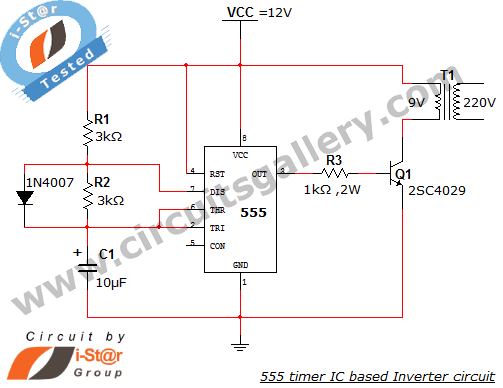
This article explains what an inverter is and how to construct a simple, low-cost 12V to 220V inverter circuit. An inverter functions as a DC to AC converter and is a valuable electronic product for compensating for emergency power...
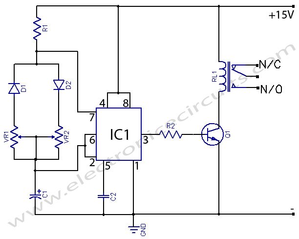
555 Timer with On-Off Delay Circuit. This circuit utilizes the commonly available 555 integrated circuit (IC) to create a timer that allows for time adjustment in both on and off states. The 555 timer is a versatile device widely used...
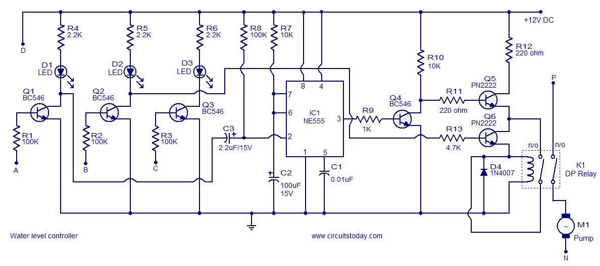
A simple water level controller circuit utilizing a 555 integrated circuit (IC) and six transistors. A relay is employed for controlling the pump motor. This water level controller circuit is designed to monitor and manage the water level in a...
This timer is designed for individuals seeking to achieve a tan while minimizing excessive exposure to sunlight. A rotary switch allows the user to set the timer based on six classified photo-types. A photoresistor adjusts the preset time value...
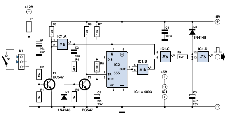
The circuit described here was designed as an addition to a remotely controlled garage door opener. The problem was that a brief burst of interference, arising from a thunderstorm or a mains spike, was enough to trigger the mechanism,...