
10 Band Graphic Equalizer Circuit

The 5-band graphic equalizer circuit based on the TL074 operational amplifier is designed to enhance audio quality by allowing users to adjust the amplitude of specific frequency ranges. This is achieved through a series of bandpass filters, each tuned to one of the designated frequencies. The low distortion and noise characteristics of the TL074 ensure that the audio signal remains clean and clear, making it ideal for high-fidelity applications.
The circuit typically includes a series of potentiometers or sliders for each frequency band, enabling precise control over the output levels. The input buffer amplifies the incoming audio signal, ensuring that it is adequately processed by the equalizer without degradation. The output buffer serves to match the output impedance and drive the subsequent stages of the audio system, maintaining signal integrity.
The design of the equalizer allows for significant customization in audio playback, making it a valuable addition to audio systems in vehicles and home audio setups. The choice of frequency bands—100 Hz for bass, 300 Hz for low midrange, 1 kHz for midrange, 3 kHz for upper midrange, and 10 kHz for treble—covers the essential range of human hearing, facilitating a balanced sound profile.
In summary, the TL074-based 5-band graphic equalizer circuit is an effective solution for enhancing audio systems, offering low noise, low distortion, and a versatile operating range, suitable for various audio applications. The accompanying wiring diagram provides essential guidance for implementing this circuit in practical applications, ensuring optimal performance and sound quality.This 10 Band Graphic Equalizer Circuit a single chip, IC TL074 to achieve a 5-band graphic equalizer for use in systems of high fidelity audio. The 5-band graphic equalizer is true for radio-cassette player and car stereos. This unit features: low distortion, low noise, wide operating voltage range (3. 5 V to 16V), low consumption (5 mA), Wide Dyna mic Range (SD = 2. 1Vrms/VCC = 8V) and built an amplifier input and output buffer. The TL074 is a five-point graphic equalizer that has integrated all the functions necessary for a cochlear implant. The IC is the system of five sounds and control input and an output buffer amplifier. The following PDF contains detailed information on the wiring diagram for the 5-band graphic equalizer with a single IC / chip (BA3812L).
The circuit shown in the table of works about five frequency bands: 100 Hz, 300 Hz, 1 kHz, 3 kHz, 10 kHz. 🔗 External reference
Related Circuits
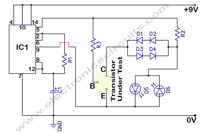
The circuit is a transistor tester schematic that indicates the condition of a transistor using two LEDs. It is designed to test a good NPN transistor. The transistor tester circuit operates by utilizing two light-emitting diodes (LEDs) to provide a...
The L29 Stepper Motor Controller IC facilitates the control of four drive signals for two bipolar and four unipolar footfall motors in a microcomputer-controlled appliance. It allows for motor operation in half-step, full-step, and wave drive modes, utilizing switch-mode...
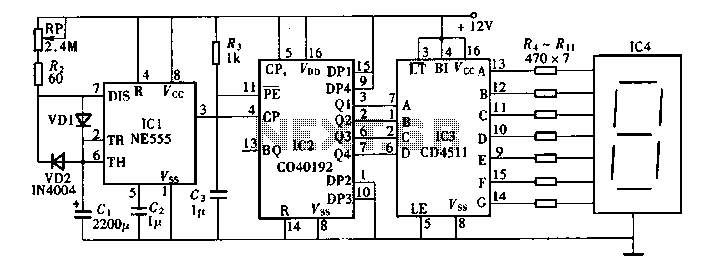
Digital timers feature a clear and precise display. They represent time intervals based on pulse signals, which are decoded by a digital device with a digital display unit. The circuit described pertains to a digital display for these timers,...
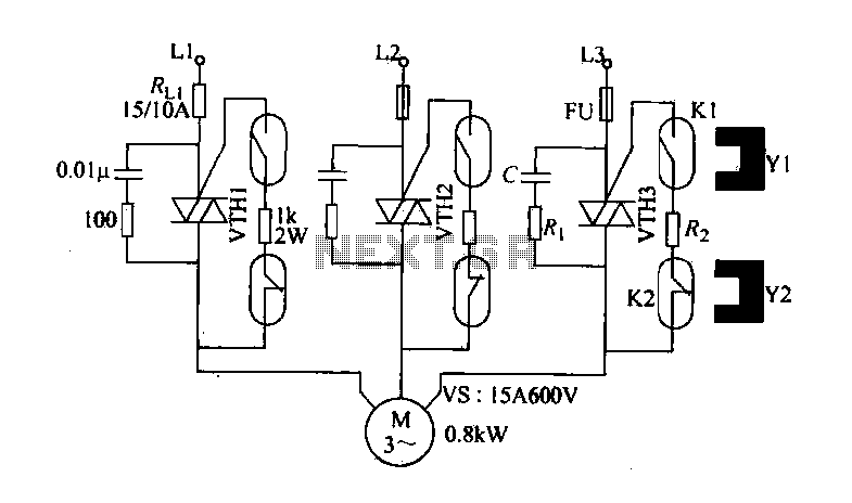
The circuit diagram illustrates a female textile machine power control circuit. VTH1-VTH3 represent TRIACs, while R and C form the absorption line. Rz serves as the triggering current limiting resistor. K1 is designated for starting the reed, and K2...
The design objective was to produce an hFE tester with switched collector currents for the DUT (Device Under Test) covering a range suitable for the selection and matching of output transistors for amplifiers such as the JLH Class-A, ESP...
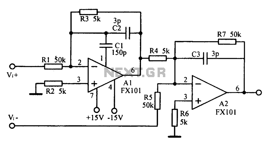
Common mode input voltage up to a difference of 100V enlarged circuit diagram. The circuit diagram described features a design capable of handling a common mode input voltage with a differential range of up to 100V. Such a configuration is...