
Antenna Tuning Unit

The circuit design of the A.T.U. is based on the principles of impedance matching, which is crucial for maximizing power transfer between the antenna and the radio receiver. The use of variable capacitors allows for fine-tuning of the resonant frequency of the circuit, ensuring that it aligns with the frequency of interest. The multi-tapped coil L1 provides versatility in tuning across a range of frequencies, while the addition of coil L2 enhances the capability to receive medium wave signals.
In practical applications, the construction of L1 and L2 is straightforward, utilizing readily available materials. The air-core inductor L1, with its multiple turns, creates a magnetic field that interacts with the incoming radio waves, allowing for selective tuning. The choice of wire gauge for both coils is critical; 22 SWG for L1 ensures a balance between resistance and inductance, while 32 SWG for L2 allows for compact winding on a ferrite core, which improves efficiency.
The A.T.U.'s performance can be further optimized by ensuring that the antenna is appropriately positioned and insulated from nearby conductive objects that may introduce noise. Additionally, the user may experiment with different lengths of wire for the antenna to find the configuration that offers the best signal quality.
Overall, this simple yet effective passive circuit enhances the listening experience for amateur radio enthusiasts, allowing for improved reception and reduced interference across various frequency bands.A simple passive (no power required) circuit to match an antenna to a radio receiver. This will be a useful addition to the short wave listener, but in addition a medium wave coil is almost used to tune the medium wave band. An aerial tuning unit (A. T. U. ) is a useful accessory for any radio listener as it matches the antennas resonant length to th e received frequency, increasing gain and reducing spurious signals. The A. T. U. does not provide gain, but provides a better match between antenna and receiver, which usually gives an increase on the signal meter of the receiver, due to the A. T. U`s resonant filter. The circuit is a standard Pi filter, consisting of two variable capacitors C1 and C2 and a multi tapped coil L1.
Switch S1 is used to select the tapping points and C1 and C2 peak up on the received signal. In this circuit an additional MW coil, L2 is used. This has a value around 200uH and can be salvaged from an old AM radio. In this position the A. T. U. can tune down to the medium waveband. To make L1, which is an air space inductor, use a 1 inch diameter former, a short section of an old brush handle made from wood is suitable. The coil is made from 22 swg enamel covered copper wire. The coil is tapped at 3, 4, 6, 8, 11, 15, 20, 30, 40, 50 and 60 turns. Coil L2 is connected in series with the 60 turn tapping point. This is wound on a 3 inch length of 3/8 diameter ferrite and has 60 turns of 32 swg, or one can be salvaged from an old AM radio.
Each tapping point is connected to the contacts on S1, to make this easier I used some small galvanised nails hammered into the wood former. Below is a picture of my A. T. U. In use this Antenna Tuner works best with a Long or Random wire antenna. As little as 5 metres of copper or aluminium wire suspended and insulated at each end in a garden will make an efficient antenna.
The noise will also be lower than if using a receiver indoors. In use, the receiver is tuned to a frequency, S1 is turned for strongest signal and then C1 and C2 adjusted for best reception. 🔗 External reference
Related Circuits
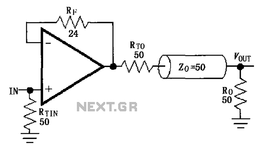
The MAX4450/4451 unity gain line is illustrated in the driving circuit. The MAX4450/4451 features internal compensation, a 24-ohm resistor in series within a feedback loop, along with capacitors and inductors that can reduce the Q value of the feedback...
This circuit illustrates the SSR (Solid State Relay) Power Control Unit Circuit Diagram. Features: The SSR control box supplies the control voltage for the relay. Component: . The SSR Power Control Unit Circuit is designed to provide efficient control of...
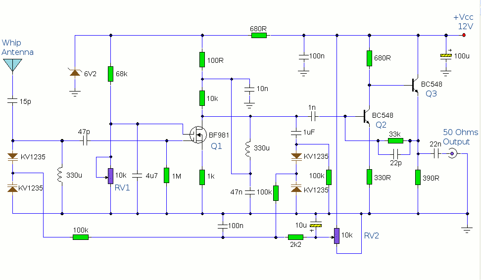
The antenna amplifier circuit comprises approximately 40 components, featuring two NPN transistors (BC548), one MOSFET (BF981), two varicap diodes (KV1235), and a 6.2V zener diode. It includes a 330µH inductor/coil, which can be modified for operation on different frequency...
A ground loop in your AV system caused by antenna connection or TV cable is very common if you have your computer connected to the same system. This type of ground loop problem can be solved by using suitable...
For several recent projects, a request was made to provide engaging and informative display units. A versatile unit was developed that can be utilized across different applications. It was designed for aesthetic appeal, capable of displaying both graphics and...
This schematic illustrates an FM, AM/MW, and SW antenna amplifier circuit, also referred to as an antenna preamplifier circuit. It is designed to enhance weak signals from FM, AM/MW, and SW bands. The circuit is straightforward and can be...