
Oscillator IIV

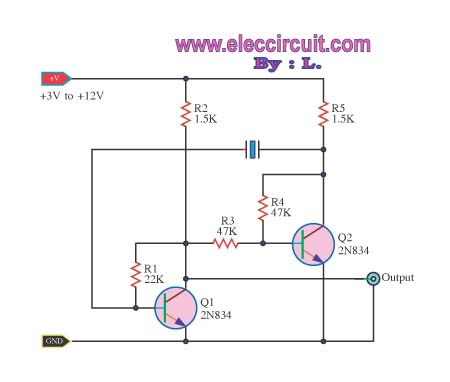
In this circuit configuration, the oscillator generates an AC signal that can interfere with the DC circuit's operation. To prevent this interference, a DC blocking capacitor is utilized. The capacitor allows AC signals to pass while blocking DC components, ensuring that the DC circuit functions correctly without being affected by the oscillator's output.
The potentiometer serves as a variable resistor that can be adjusted to control the amplitude of the AC signal reaching the load. Connecting the DC blocking capacitor in series with the wiper arm of the potentiometer allows for fine tuning of the output signal. The addition of a 10 kΩ potentiometer enhances the control over the signal, enabling precise adjustments to the output level. This configuration is particularly useful in applications where signal integrity is crucial, such as in audio processing or signal conditioning circuits.
The overall design ensures that the oscillator can effectively interface with the DC circuit while maintaining the desired output characteristics, providing flexibility in signal management and control. Proper selection of the capacitor value is essential to match the frequency response of the oscillator, while the potentiometer should be chosen based on the required range of output adjustment. This setup emphasizes the importance of component selection and configuration in achieving optimal circuit performance. When the oscillator is connected to a dc circuit then connect a dc blocking capacitor in series with the potentiometer's wiper arm. If fine output control is desired, add the 10 potentiometer.
Related Circuits
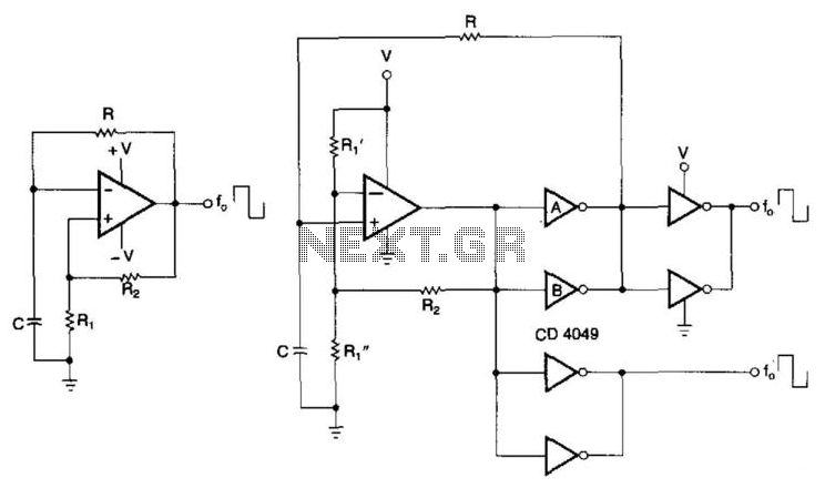
CMOS buffers added to an operational amplifier oscillator enhance performance, primarily due to the asymmetry and variability of the operational amplifier's output saturation voltages. The integration of CMOS buffers into an operational amplifier (op amp) oscillator circuit serves to significantly...

In conventional triangular-wave oscillators, hysteresis from positive feedback in the Schmitt trigger determines the voltage levels and amplitude of the triangular waves. With this topology, it is difficult to independently vary the voltage levels and amplitude of the output...
The voltage Vc1 increases linearly when the pull-up resistor RA in the monostable circuit is replaced with a constant current source, resulting in a linear ramp. The circuit for generating the linear ramp and the corresponding waveforms are illustrated...

The following diagram illustrates the schematic of a simple, easily tuned adjustable sine and square wave oscillator. This circuit generates sine and square wave signals at frequencies ranging from below 20 Hz to above 20 kHz. The advantage of...
An oscillator circuit of this nature is often utilized as a clock circuit. This circuit employs a crystal frequency control with a stability of one million hertz. An oscillator circuit designed for clock applications typically generates a periodic signal, which...
The objective is to test a Wien bridge oscillator and ensure its proper functionality. There is a study of relevant material, but some concepts remain unclear. The Wien bridge oscillator is a type of electronic oscillator that generates sine waves....