
100W Inverter Circuit 12VDC to 220VAC

The 100W inverter circuit is designed to efficiently convert a low-voltage DC input into a standard AC output suitable for powering household appliances. The core component of this inverter is the CD4047 integrated circuit, which functions as an oscillator. It generates a 50Hz sine wave signal, which is essential for mimicking the utility power supply frequency.
The generated sine wave signal is then fed into a power transistor, specifically the 2N3055. This transistor operates in the linear region, allowing it to amplify the current of the sine wave signal. The 2N3055 is capable of handling high currents, making it an ideal choice for applications requiring substantial power output.
Following the amplification, the signal is directed to a transformer. The transformer plays a crucial role in stepping up the voltage from the low DC input level to the desired high AC output voltage of 220V. The turns ratio of the transformer is selected based on the input and output voltage requirements, ensuring that the output waveform remains as close to a pure sine wave as possible.
In addition to these components, the circuit may include various passive components such as resistors and capacitors for signal conditioning, as well as protective elements like diodes to prevent back EMF from damaging the circuit during operation. Proper heat dissipation measures should also be implemented for the 2N3055 transistor, as it can generate significant heat under load. Overall, this inverter circuit is a practical solution for converting DC power to AC power for use in various applications.Here the schematic diagram of 100W Inverter Circuit which will convert 12VDC input to be 220VAC output. The circuit built based IC CD4047 to generate sine wave signal 50Hz and then the power transistor 2N3055 will boost the signal so that the signal have high power (high electric current).
Then the sine wave signal will be stepped up by the transf ormer. 🔗 External reference
Related Circuits
An RF probe is a circuit designed for testing equipment that converts high-frequency signals into DC voltage. This conversion facilitates the measurement of RF voltages for testing or adjusting transmitters, receivers, and modulators. The RF probe circuit outlined here...
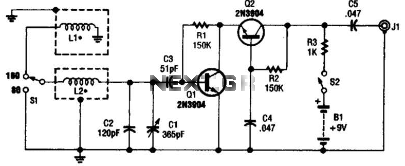
This antenna may assist in minimizing power-line noise. It consists of a plastic hula hoop or conduit with a diameter of 3 feet, which is covered with aluminum foil to serve as a shield for LI and L2. LI...
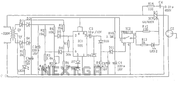
An automatic power protection circuit is presented. This protection includes a step-down rectifier circuit, an overvoltage and undervoltage detection circuit, and a delay switch control circuit. The step-down circuit is responsible for the entire rectifier circuit's DC voltage. The automatic...
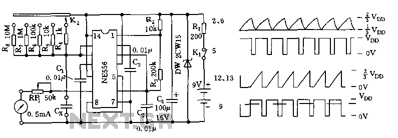
The tester comprises a dual time base circuit using a 556 timer and various RC components. The right side of the circuit features the 556 timer (556 1/2) along with resistors R2, R3, capacitors C2, C3, and additional components...

This liquid detector circuit diagram is designed using common electronic components. The liquid detector can activate an active buzzer to produce sound when a certain water level is reached. Since the water sensor and control circuit for the buzzer...
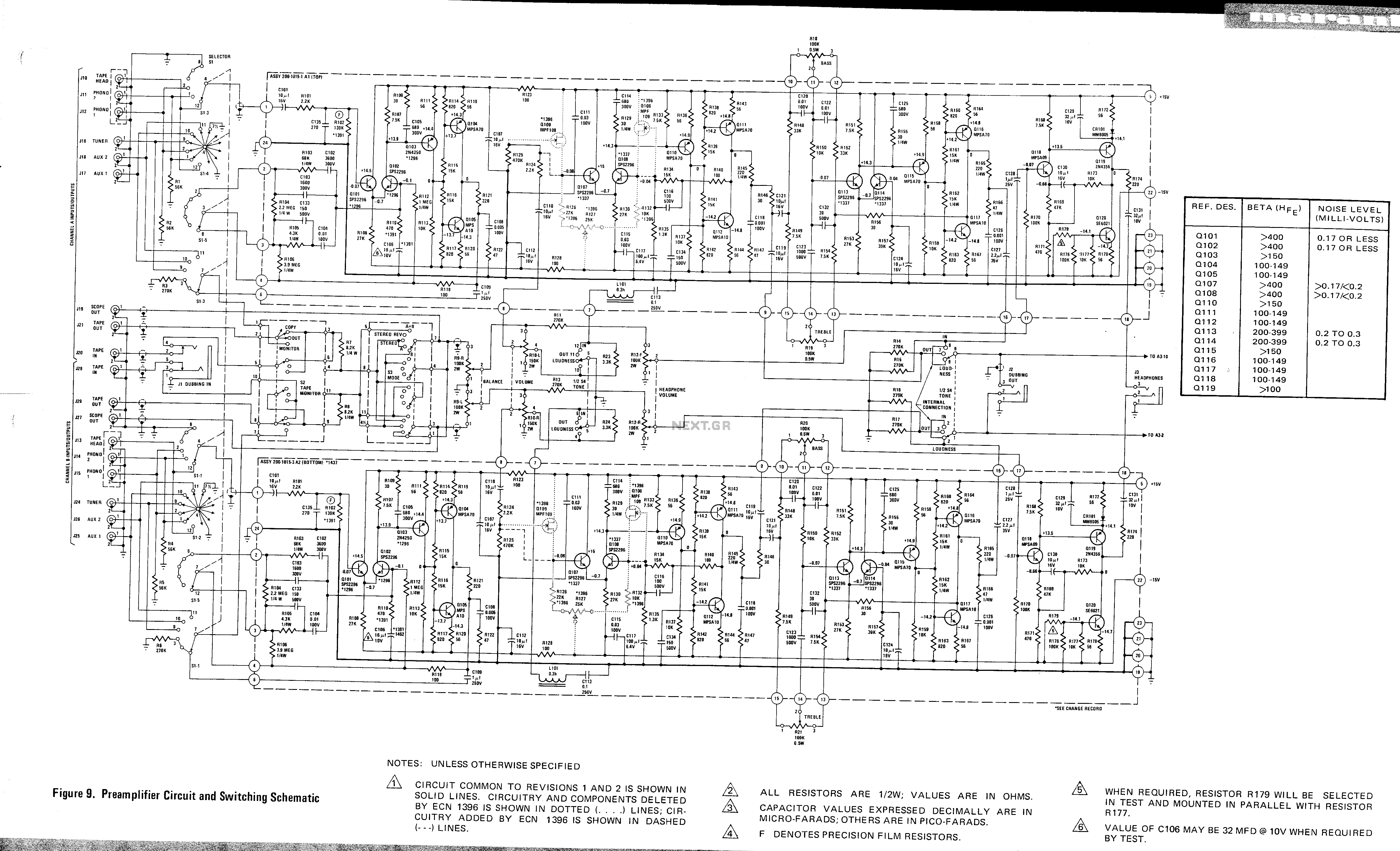
This is a preamplifier circuit and switching schematic for the Marantz Model 33. The Marantz Model 33 preamplifier circuit is designed to amplify low-level audio signals from various sources before sending them to a power amplifier. The schematic typically includes...