
Digital pressure measuring circuit

The AD7710/7715/7730 series of integrated circuits are designed for precise digital pressure measurement and signal conditioning applications. These multifunctional devices are equipped with a robust digital interface that facilitates communication with microcontrollers or other digital systems through a control port. The inclusion of a clock generator ensures that the internal operations of the ICs are synchronized, enabling accurate timing for data acquisition and processing.
The digital filter incorporated within these ICs plays a crucial role in minimizing noise and enhancing the signal quality before it undergoes further processing. This is particularly important in pressure measurement applications where ambient noise can significantly affect the readings. The amplitude modulation (A/modulation) feature allows for effective signal conditioning, ensuring that the output signal is optimized for subsequent analysis.
A programmable gain amplifier (PGA) is integrated into the circuit to allow for flexible signal amplification, accommodating a wide range of input signal levels. This feature is essential for applications that require precise measurement across varying pressure ranges. The analog-to-digital (A/D) converter converts the conditioned analog signal into a digital format, enabling easy integration with digital systems for further processing and display.
The internal function block diagram illustrates the various components and their interconnections within the IC, providing insight into the operational flow of the device. The pin functions are meticulously defined to facilitate proper connections in application circuits, ensuring that users can effectively utilize the device in their specific applications. The accompanying application circuit diagram serves as a practical guide for implementing the IC in real-world scenarios, showcasing typical configurations and component values necessary for optimal performance.
Overall, the AD7710/7715/7730 series offers a comprehensive solution for digital pressure measurement, combining advanced signal conditioning features with user-friendly interfacing capabilities, making it suitable for a wide range of industrial and commercial applications.Digital pressure measuring circuit AD7710/7715/7730 multifunction digital sensor signal conditioning ICs. They integrate a digital interface with the control port, a clock gene rator, a digital filter, A/modulation, programmable gain amplifier, A/D converter and other electric path. Their internal function block diagram, pin functions and the corresponding application circuit diagram in Fig.
Related Circuits
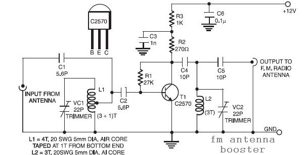
This is a low-cost FM antenna booster that can be used to listen to programs from distant FM stations clearly. The antenna FM booster circuit comprises a... The FM antenna booster circuit is designed to enhance the reception of FM...
This circuit generates a two-tone effect similar to the cuckoo song. It can be utilized for doorbells or other applications due to its integrated audio amplifier and loudspeaker. When used as a sound effect generator, it can be connected...
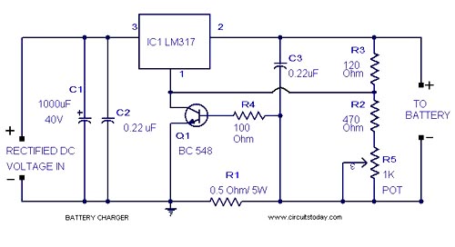
A simple lead-acid battery charger circuit with a diagram and schematic using the IC LM317, which provides the correct battery charging voltage. This lead-acid battery charger should be supplied with an input of 18 volts to the IC. The lead-acid...
The circuit depicted in Figure 3-49 illustrates an autotransformer that is controlled by a time relay (KT). The delay time set by the KT relay corresponds to the motor's startup duration. The circuit utilizes an autotransformer, which is a type...
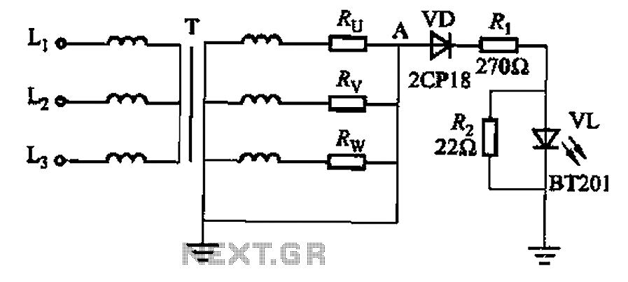
It is well understood that if the power transformer neutral line is disrupted, an unbalanced three-phase load can easily result in overvoltage conditions, potentially damaging electrical equipment such as household appliances and lamps. The neutral circuit alarm system is...
The circuit operates using pulse position modulation, which is a method distinct from the more commonly utilized pulse width modulation for speed control. A 555 timer is employed as a square wave modulator, generating output pulses with a fixed...