
120Ac Shimmering Light Circuit

This circuit design effectively transforms a conventional incandescent bulb into a dynamic light source capable of shimmering or blinking. The SCR plays a crucial role in modulating the lamp's brightness by controlling the power delivered to it. The full-wave rectification process using diodes D1 and D2 ensures that the AC input is converted to a usable DC output, which is essential for the operation of the capacitor and the subsequent oscillator circuit.
The oscillator's frequency, which is adjustable via potentiometer P1, allows for customization of the shimmering effect. This feature enables users to select a preferred shimmer rate, adding versatility to the lighting effect. The inclusion of capacitor C1 serves to smooth out the voltage fluctuations, providing a stable DC voltage to the SCR and ensuring consistent operation of the circuit.
Safety precautions are paramount when working with circuits connected to the AC mains. It is essential to ensure that all components are rated for the appropriate voltages and currents, and that the assembly is securely housed to prevent accidental contact with live electrical parts. The recommendation to use a wooden or plastic enclosure further enhances safety by providing insulation from electrical shock hazards. Overall, this circuit serves as an innovative solution for creating decorative lighting effects while emphasizing the importance of safety in electrical design. You can turn any ordinary household bulb into one that shimmers or blinks. This circuit works on any incandescent light up to 200 W, arid runs on standard 120 Vac. The circuit uses an SCR to cause an ordinary lamp to sliimmer. Note that one side of the lamp is connected directly to 120 Vac, and the other side of the lamp goes to the cathode of the SCR. As ac voltage is brought into the circuit through the line cord, it is full-wave rectified by diodes D1 and 1)2.
That changes the ac to dc, and a portion of that dc voltage is applied to capacitor CI through R2. Diode D3 blocks the (+) dc voltage so that only the voltage from the path of R1 and D3 is clear. That forms an oscillator, which has a frequency determined by the setting of potentiometer PI (becausc the other components have fixed values). Remember to use extreme caution when using a device that connects to the ac line. Never use it outside or near water and always mount the entire kit inside a wooden or plastic (insulated) box to prevent any contact with the ac voltage.
Related Circuits
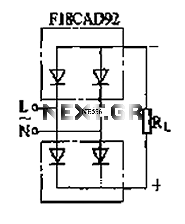
The circuit depicted is a single-phase bridge rectifier. It consists of arms with a cathode (negative electrode) and parallel anodes (positive electrodes) arranged in a configuration that connects multiple rectifier modules to form a bridge, commonly referred to as...

This circuit is beneficial for amateur radio operations in VHF and UHF frequencies, where a mast-mounted antenna preamplifier is employed for reception. The kit manages the transmit-receive (T-R) switching and relay sequencing to prevent high RF levels from being...

This high voltage source consists of an inverter built around a transistor that generates pulses of 150V. These pulses are supplied to an inverter made of a thyristor and a capacitor, which is connected in series with transformer T2....

This receiver is a modification of Charles Wenzel's Two Transistor Reflex Radio. Instead of a ferrite AM loopstick antenna, a magnetic loop antenna is used, and an LM386 amplifier stage has been added to drive an 8-ohm speaker. A...

The CMOS amplifier is biased into the linear region by resistor RB. The pi-type crystal network (C1 and C2, and XTAL) provides the 180-degree phase shift at the resonant frequency, which causes the circuit to oscillate. The described circuit utilizes...

This circuit combines two or more audio channels into a single channel (for example, converting stereo to mono). It is capable of mixing multiple channels while consuming minimal power. The schematic illustrates two inputs, but additional inputs can be...