
12V Flourescent Lamp Inverter

The circuit design for driving fluorescent tubes from a battery source consists of a robust inverter system capable of efficiently converting low-voltage DC to high-voltage AC, suitable for the operation of fluorescent lamps. The inverter utilizes a combination of integrated circuits and transistors to achieve this conversion. The first stage, the DC-DC inverter, is responsible for stepping up the input voltage to a level sufficient for the fluorescent driver. This stage typically employs a feedback mechanism to regulate output voltage and maintain efficiency under varying load conditions.
The fluorescent tube driver circuit is designed to produce an alternating current that matches the requirements of the fluorescent tubes. This involves generating high-voltage AC from the previously stepped-up DC, which is critical for the ionization of the gas within the tubes, enabling them to emit light. The use of a totem-pole output configuration allows the circuit to efficiently drive the load while minimizing power losses.
The inverter's efficiency is paramount, as it directly impacts the performance and brightness of the fluorescent tubes. Many commercially available models fall short of delivering the full rated power to the tubes, resulting in lower light output. This is a significant consideration for applications requiring optimal lighting levels, such as in commercial spaces.
Safety precautions are essential when working with high-voltage circuits. The design must include protective elements to prevent accidental contact with high-voltage outputs. Additionally, the circuit should incorporate fuses or circuit breakers to safeguard against overcurrent conditions, which could lead to equipment damage or fire hazards.
In conclusion, the design and implementation of a battery-powered fluorescent lighting system require careful consideration of efficiency, safety, and performance. Proper circuit design and component selection are critical to achieving a reliable and effective lighting solution.Fluorescent tubes use far less energy than incandescent lamps and fluorescent tubes last a great deal longer as well. Other advantages are diffuse, glare-free lighting and low heat output. For these reasons, fluorescent lighting is the natural choice in commercial and retail buildings, workshops and factories.
For battery-powered lighting, fluores cent lights are also the first choice because of their high efficiency. The main drawback with running fluorescent lights from battery power is that an inverter is required to drive the tubes. Fig. 1: two switch-mode circuits are involved here: the DC-DC inverter involving IC1, Q1 & Q2 and the fluoro tube driver which converts high voltage DC to AC via IC3 and Q3 & Q4 in a totem-pole circuit.
Inverter efficiency then becomes the major issue. There are many commercial 12V-operated fluorescent lamps available which use 15W and 20W tubes. However, it is rare to see one which drives them to full brilliance. For example, a typical commercial dual 20W fluorescent lamp operating from 12V draws 980mA or 11. 8W. Ignoring losses in the fluorescent tube driver itself, it means that each tube is only supplied with 5. 9W of power which is considerably less than their 20W rating. So while the lamps do use 20W tubes, the light output is well below par. This circuit generates in excess of 300V DC which could be lethal. Construction should only be attempted by those experimenced with mains-level voltages and safety procedures
🔗 External reference
Related Circuits
This document presents a straightforward and practical schematic for a 12V to 3V converter circuit. The output current of the circuit is approximately 1A. The 12V to 3V converter circuit is typically designed using a linear voltage regulator or a...
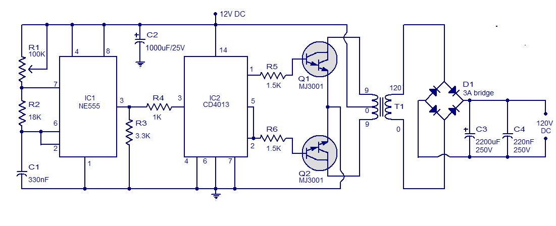
This is a simple circuit designed to convert 12V DC to 120V DC. The circuit comprises two main phases: the inverter stage and the rectifier and filter stage. The NE555 integrated circuit (IC1) is configured as an astable multivibrator,...
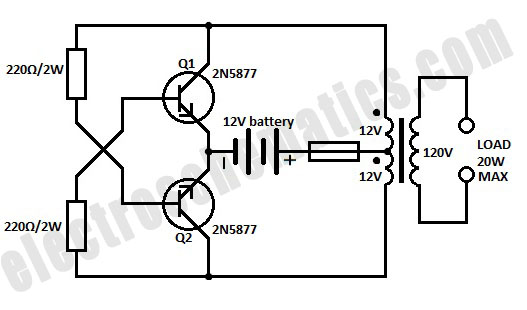
A simple 12-volt inverter circuit. This 120V AC power source is constructed using a basic 120V:24V center-tapped control transformer and four additional components. The circuit generates a clean 200-V peak-to-peak square wave at 60 Hz and is capable of...
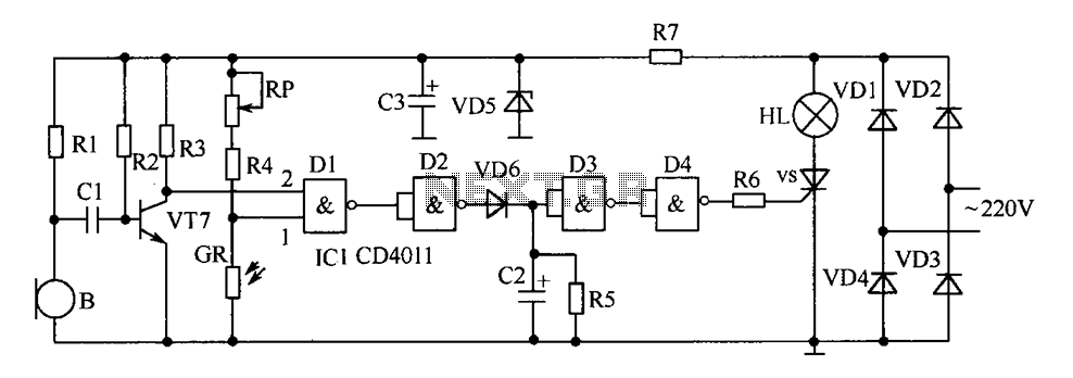
The delay-saving lamp circuit functions as a sound and light control delay energy-saving lighting system. It can directly replace a standard light switch without modifying the existing lighting circuits. In bright or daytime conditions, the sound control feature ensures...
This is an astable multivibrator (oscillator) circuit utilizing a CMOS inverter. The circuit employs the CD4007 or MC14007 components. It operates within a frequency range of... The astable multivibrator circuit is designed to generate a continuous square wave output without...
The charger consists of two stages: The first is a capacitive voltage doubler, which uses a 555 timer IC driving a pair of transistors connected as emitter followers, which in turn drive the voltage doubler proper. The doubler has...