
15W Inverter Circuit 12VDC to 120VAC

The 15W inverter circuit utilizes a PNP power transistor, specifically the TIP32, which is designed to handle the necessary current and voltage levels for efficient operation. The circuit configuration is intended to convert a DC input into a square wave AC output, suitable for powering various devices, albeit with some limitations in terms of output waveform quality.
The square wave output is characterized by its abrupt transitions between high and low states, which can introduce audible hum when connected to audio equipment. This is due to the harmonic content of the square wave, which includes a fundamental frequency and its odd harmonics. To mitigate this issue, the output capacitor's value can be increased to 0.47µF, which helps to filter some of the high-frequency noise and smooth the output waveform, thus reducing the hum.
The transformer plays a critical role in this inverter circuit. It is specified to have a center-tapped secondary winding rated at 24 volts and 2 amperes. This configuration allows for the generation of a dual voltage output, providing both positive and negative halves of the square wave. The center tap serves as a ground reference, which is essential for the proper functioning of the circuit.
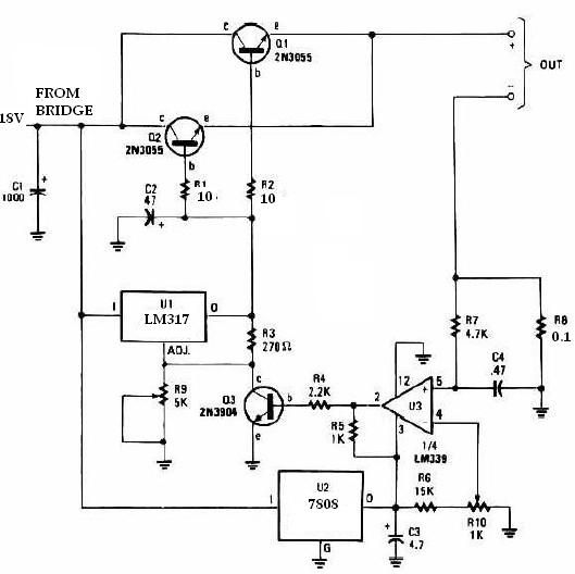
In summary, this 15W inverter circuit is a practical solution for converting DC power to AC, utilizing a PNP transistor and a transformer. While the square wave output may introduce some noise in sensitive audio applications, adjustments to the output capacitor can help mitigate these effects, making the circuit more suitable for a wider range of applications.This is the schematic diagram of 15W inverter circuit. The circuit is based PNP power transistor such us TIP32 and other similar transistors. This inverter is producing square wave, there may be some noticeable hum on audio units which powered using this inverter circuit. To reduce some of the hum, you may increase the value of the output capacito r (. 47uf capacitor). The transformer will be a 24 Volt 2 ampere center tapped secondary. 🔗 External reference
Related Circuits
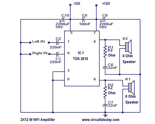
A simple Hi-Fi amplifier circuit diagram with a schematic for creating an audio amplifier design using the TDA 2616 IC. This is a stereo power amplifier suitable for radio, tape, and television applications, delivering 2 x 12 watts, totaling...
This circuit allows the use of an inexpensive loudspeaker as a microphone. Sound waves that reach the speaker cone create fluctuations in the voice coil. The movement of the voice coil within the speaker's magnetic field generates a small...

This circuit is a touch switch circuit, similar to a touch door alarm. It utilizes a 555 timer as the core component of the touch switch circuit. The operation begins when the plate is touched, triggering the 555 timer....
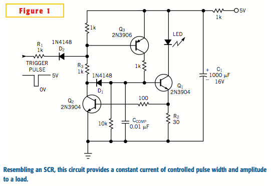
A typical silicon-controlled rectifier (SCR) requires a trigger current to latch on. Once the device is latched, the current flowing through the SCR is determined only by the external component values. The SCR lacks the ability to limit current...
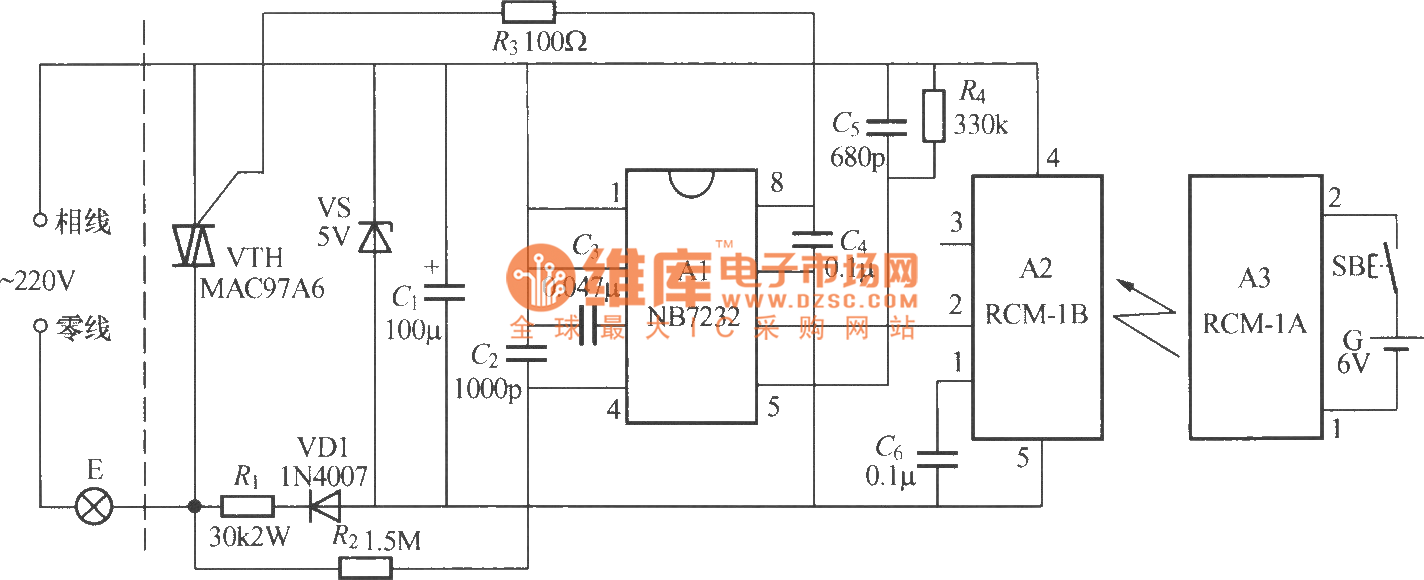
The diagram above illustrates a radio remote control dimmer circuit. This circuit utilizes a micro radio transmit/receive module in conjunction with a light modulation ASIC, resulting in a compact and easily producible design. It operates reliably and features a...
This universal battery charger utilizes the LM317 voltage regulator and features an adjustable output voltage along with a constant-current charging circuit, making it suitable for charging most NiCad batteries and various other battery types. The LM317 universal battery charger...