
12V to +/- 20V DC Converter Circuit

The DC to DC converter circuit operates by utilizing the TL494 IC, which is well-regarded for its versatility in managing power supply applications. The adjustable frequency capability enables fine-tuning of the PWM signal, allowing for optimal performance based on the load requirements. The output voltage can be finely controlled to ensure that the desired +/-20 V DC is achieved, making this converter suitable for various applications where specific voltage levels are necessary.
The TL494's PWM output controls the switching of the MOSFETs, which are essential for the conversion process. The TPS2811P driver is specifically chosen for its ability to efficiently drive the MOSFETs, ensuring that they switch on and off quickly to minimize losses and improve overall efficiency. The use of two MOSFET transistors in the inverter stage allows for a push-pull configuration, which is beneficial for generating a symmetrical output voltage.
In practical applications, the circuit may include additional components such as inductors for energy storage, capacitors for filtering, and diodes for rectification, depending on the specific design requirements. The layout of the circuit should be carefully considered to minimize electromagnetic interference (EMI) and optimize thermal management, especially in high-power scenarios. The final output stage may also include feedback mechanisms to monitor and regulate the output voltage, ensuring stability under varying load conditions. Overall, this DC to DC converter circuit is a robust solution for applications requiring precise voltage regulation and high efficiency.DC To DC Converter circuit used to be an convert voltage DC to DC with different concepts. DC to DC converter circuit +12 V to + /-20V is working to change the battery voltage from 12V DC to 20V DC voltage symmetrical. DC to DC converter circuit is often applied to the power amplifier udio on car audio systems. DC to DC converter circuit uses a TL 494 IC as power plsa for the converter. TL494 IC is a PWM controller with an adjustable frequency from 40-60Hz through a potentiometer. Then from the TL494 PWM signal is given to the driver MOSFET inverter TPS2811P to be given to the power inverter with 2 units of MOSFET transistors. Circuit details can be seen in the figure following the DC to DC converter. 🔗 External reference
Related Circuits
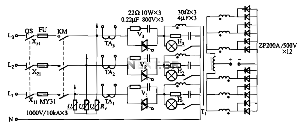
A 1500A-7V phase thyristor power regulator circuit is designed for plating applications. It consists of three major components: the main circuit, the control circuit, and the protection circuit. The control circuit includes a trigger circuit, a synchronous power supply,...
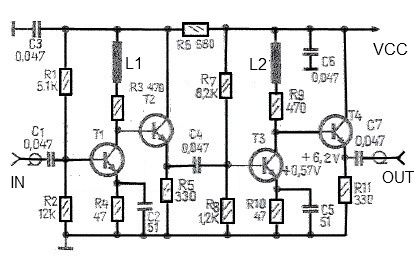
This antenna amplifier is effective for the frequency range of 35 kHz to 150 MHz. The circuit utilizes transistors and features a low 3 dB non-linearity along with a high gain of 43 dB. The input and output impedance...
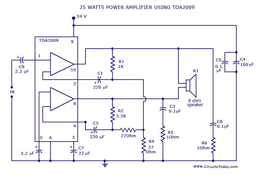
Power amplifier circuit diagram with schematics. This simple audio power amplifier circuit is designed for 25 watts output power using TDA 2009 IC, which has two channels (stereo), 12.5 W for each channel. The described power amplifier circuit utilizes the...
VOX is a voice-activated switch commonly used with microphones as an alternative to traditional push-button switches. The VOX can be connected to various audio equipment featuring an external speaker for coupling. The activation threshold is adjusted using the volume...
The circuit amplifier and attenuator control video detector consists of a composition for the synchronization channel. The synchronization interval is where the gain circuit is increased. The described circuit involves an amplifier and an attenuator that work together to control...
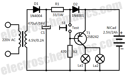
This low-cost automatic emergency lighting circuit activates a lamp during power failures. It is powered by a NiCad battery that is charged by the mains. The automatic emergency lighting circuit is designed to provide illumination during unexpected power outages. The...