
12Vdc Mobile Battery Charger

This circuit is designed for efficient charging of nickel-cadmium (NiCad) batteries, which are commonly used in various applications due to their reliability and performance characteristics. The square-wave oscillator (VI) is a critical component that generates a square wave signal, which is essential for boosting the voltage from the 12-V automotive supply. The diodes (D1 and D2) are employed to rectify the oscillating signal, ensuring that the output voltage exceeds 20 V DC, which is necessary for effective charging of the NiCad batteries.
The inclusion of switch S1 offers flexibility in the circuit operation. When S1 is open, the circuit operates without the boosted voltage, allowing for standard charging conditions. This feature is particularly useful in applications where the higher voltage is not required or could potentially damage sensitive components.
Transistor Q1 acts as a current regulator, which is vital for controlling the charging rate of the battery. By maintaining a consistent current flow, Q1 helps prevent overcharging, which can lead to battery damage or reduced lifespan. The selection of resistor R4 plays a significant role in determining the precise charging current. Users can select R4 from a predefined table based on the desired charging current, or utilize a rotary selector switch for adjustable settings. This adaptability allows for fine-tuning of the charging process, accommodating different battery capacities and conditions.
Overall, this circuit represents a robust solution for charging NiCad batteries from an automotive power source, combining simplicity with effective voltage boosting and current regulation. The design emphasizes safety and versatility, making it suitable for various charging applications. This circuit provides up to 20 V output from a 12-V automotive supply, to enable constant current charging o f Nicad battery assemblies up to about 18 V total. VI forms a square-wave oscillator, Dl and D2, coupling this square wave to the 12-V battery supply to obtain over 20 Vdc. If this is not needed, SI is left open. Ql forms a current regulator to determine the charging rate of the rechargeable battery. R4 is selected from the table or it can be switched with a rotary selector switch.
Related Circuits
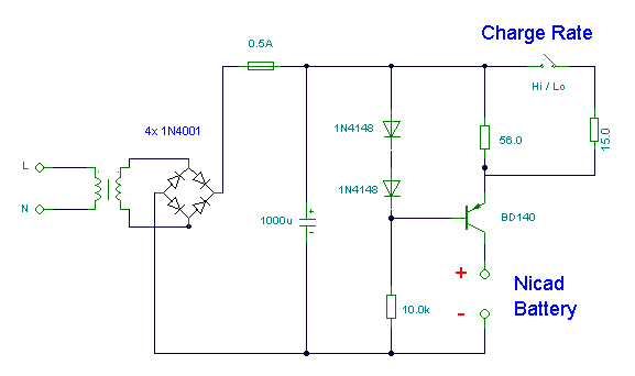
This simple charger utilizes a single transistor as a constant current source. The voltage across a pair of 1N4148 diodes biases the base of the BD140 medium power transistor. The base-emitter voltage of the transistor and the forward voltage...
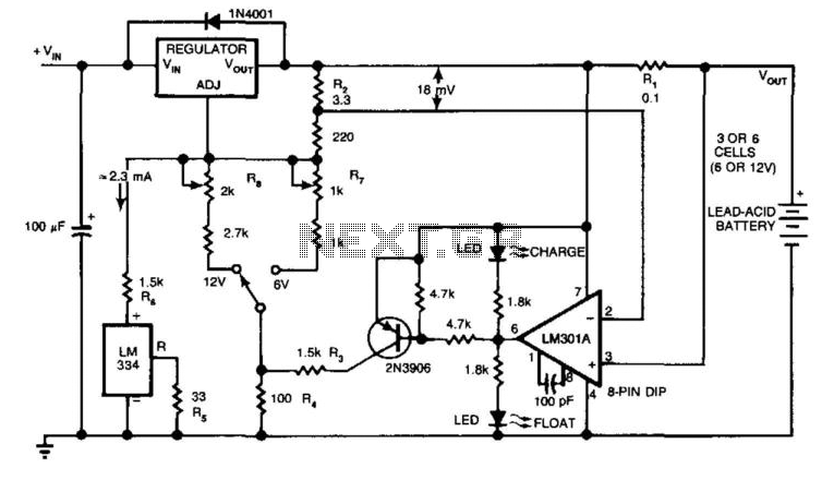
The circuit provides an initial charging voltage of 2.5 V per cell at 25°C to quickly charge a battery. The charging current decreases as the battery charges, and when the current falls to 180 mA, the charging circuit lowers...
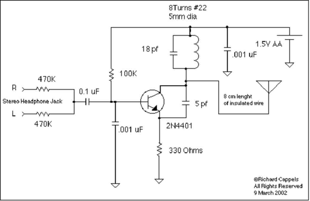
This device is designed to rebroadcast the output of a CD player, television receiver, or radio receiver. It allows for mobility within the home, enabling users to enjoy their favorite programs without being tethered to the source. The effective...

This circuit performs a rapid battery test without requiring a power supply or costly moving-coil voltmeters. It features two ranges: when SW1 is configured as depicted in the circuit diagram, the device can test batteries ranging from 3V to...
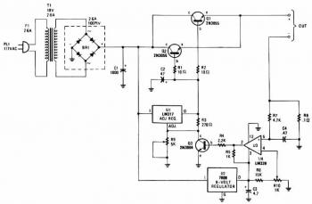
The charger is capable of charging a single cell or multiple series-connected cells with a maximum voltage of 18V. Power transistors Q1 and Q2 are configured as series regulators to manage the output voltage and charging current of the...
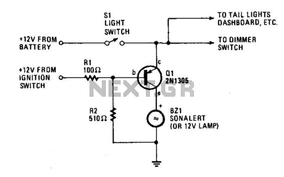
The circuit provides a visible or audible warning when the headlights are on. It utilizes a 2N1305 transistor as a switch to activate either a Sonalert tone generator or a small 12-V lamp. The operating current for the transistor...