
15v battery operated fm

To optimize performance, wind the coil on a 4 or 5 mm diameter Philips screwdriver or similar object, then remove it. Vinyl insulated #24 gauge wire and #30 enameled wire were utilized. The coil's length was adjusted to tune the transmitter to an unused frequency on the FM band. The coil is secured with hot glue. If a spectrum analyzer or frequency meter is unavailable, a good-quality FM receiver can be used to verify the tuned frequency. While adjusting the coil, it is important to remember that all superheterodyne receivers have image frequencies. If multiple adjustments result in the transmitter being detected at the same frequency on the receiver, it may be necessary to take a short walk to determine which adjustment drops out first; this would indicate the image frequency, as the receiver's front end (if it has a tuned front end) will reduce sensitivity to the image. Various transistor types can be effectively used in this application. The device functions as an oscillator, with frequency modulation achieved by varying the base-collector voltage, which modulates the depth of the depletion region of the reverse-biased base-collector junction. This results in a change in capacitance at the collector, thereby altering the oscillation frequency of the receiver circuit. The 2N4401 transistor was used due to availability, but the 2N3904 and MPSH34 are also suitable options.
The circuit design includes a basic oscillator configuration with a transistor operating in the common emitter mode. The input signal from the audio source is coupled to the base of the transistor through a capacitor, allowing audio modulation of the carrier frequency generated by the oscillation of the transistor. The output is then fed through an LC tank circuit, which consists of the coil and a capacitor, to establish the desired oscillation frequency. The antenna, formed by the coil, radiates the modulated signal, allowing for reception by standard FM radios within the specified range.
Power supply considerations include the use of a single AA battery, which provides a compact and portable power source. The low current draw ensures extended battery life, making this transmitter practical for continuous use. The use of hot glue for securing components enhances durability and allows for easy adjustments during the tuning process. The overall simplicity of the design permits easy assembly and modification, making it accessible for hobbyists and electronics enthusiasts.This accomplishing is acclimatized to rebroadcast the achievement of a CD player, television receiver, or radio receiver. I use it so that I can move about the abode and accept to my admired programs after advancing others.
Within and the house, I acquisition that I can get 10 to 20 meters abroad from the transmitter with the baby abridged FM rece iver I backpack in my shirt pocket. Your breadth may vary. The transmitter as congenital and pictured beneath (the transmitter is in the balloon of hot cook cement on the end of the array holder) does not accept an on-off switch. I put a 1. 5 AA corpuscle that was run bottomward too far to run my CD amateur in this transmitter and it ran for over a ages afore I replaced it.
The one in the transmitter at this moment has been active it continuously for over three months. Current draw is alone about a milliamp with a new array (assuming you don`t accept a super-high beta transistor in which case the abstract absolute is about 2. 5 ma). An on-off swich is not necessary, admitting it may amuse an affecting need. Tips to get it working: Wind the braid on a 4 or 5 mm bore Philips brand screwdriver or agnate anatomy again blooper it off.
I acclimated some vinyl cloistral #24 amalgamation wire as able-bodied as #30 enameled wire. In both cases, I played with the breadth of the braid to tune the transmitter to a asleep atom on the FM band. The braid is captivated in abode with hot cook glue. If you don`t accept a spectrum analyzer or abundance meter, use a good-quality FM receiver to accomplish abiding its acquainted area you anticipate it is.
While adjusting the coil, accumulate in apperception that all superheterodyne receivers accept images. If you acquisition that two or added adjustments accomplish the transmitter appearance up on the aforementioned atom on the receiver, it ability be all-important to booty a abbreviate airing and acquisition out which acclimation drops out aboriginal -this would be the image, because the receiver`s advanced end (if it has a acquainted advanced end) will abate its acuteness to the image.
Many kinds of transistors will assignment accomplished in this application. After all, its alone an oscillator (frequency accentuation is acquired my modulating the base-collector voltage, thereby modulating the abyss of the burning band of the reverse-biased base-collector junction, which after-effects in a change in capacitance at the collector, which after-effects in a change the beating abundance of the beneficiary circuit. ). I acclimated an 2N4401 because I accept a lot of them. I like 2N3904 and MPSH34 for this too. 🔗 External reference
Related Circuits

Many blind and deaf-blind individuals utilize portable electronic devices to aid their daily activities; however, they face challenges when testing the batteries used in these devices. While talking voltmeters exist, there is no equivalent device suitable for deaf-blind users....
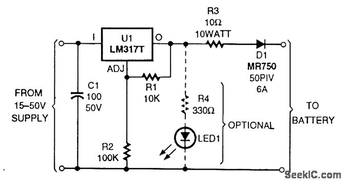
The circuit is based on an LM317T adjustable voltage regulator. The output voltage (VOUT) is defined by the formula VOUT = 1.25 (1 + R2/R1). A 10-kΩ resistor is selected for R1 and a 100-kΩ resistor for R2, allowing...

A 12V battery charging circuit is presented, featuring a straightforward diagram for a rectifier. The lead-acid trickle charger circuit is detailed along with its rectifier. The 12V battery charging circuit is designed to charge lead-acid batteries using a trickle charging...
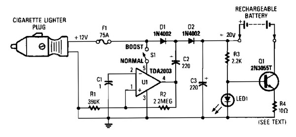
V1 creates a square wave oscillator, while D1 and D2 couple this square wave to a 12-V battery, raising the voltage to over 20 VDC. If this elevated voltage is not required, S1 can remain open. Q1 functions as...
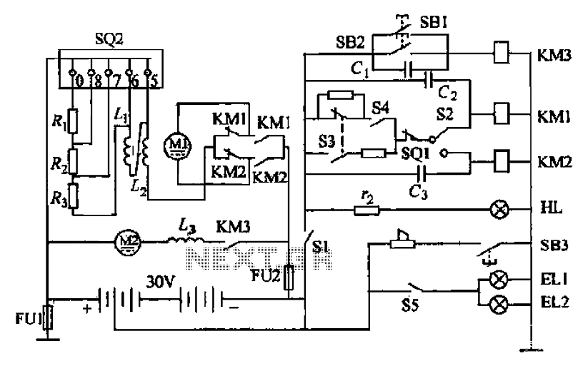
Battery forklifts are commonly used as stacking and handling tools in railway stations, docks, and warehouses. The battery shape and electrical control circuitry are depicted in the schematic. The system consists of batteries connected in series to form a...

The battery-operated toy has malfunctioned, necessitating repair. Upon disassembly, the battery compartment may be disconnected from the circuitry, or the batteries might be depleted. A solution is to implement a switchable power supply designed to replace one to six...