
136 kHz QRSS receiver
The described circuit outlines a simple yet effective receiver design intended for digital modes, utilizing a combination of analog components and software capabilities. The front-end selectivity is crucial for filtering out unwanted signals, allowing the receiver to focus on the desired frequency range. The use of a 1.4 MHz crystal filter, despite its size, indicates a design choice that prioritizes bandwidth over size, ensuring that the receiver can effectively handle the 136 kHz band.
Transistor Q100 plays a pivotal role in this circuit, serving as a gain stage that enhances the signal coming from the crystal filter and compensates for any losses incurred in the filtering and mixing stages. The inclusion of a manual gain adjustment via a knob linked to V300 allows for user control over the signal strength, which is essential in optimizing performance based on varying signal conditions.
The recommendation to insert a 6 to 10 dB pad between C104 and MIX100 in the case of intermodulation problems highlights the importance of maintaining signal integrity throughout the processing stages. This additional attenuation can help mitigate distortion and improve overall receiver performance.
The operational voltage requirement for the gain adjustment circuit is a critical design consideration. Ensuring that the voltage remains above 2.0 V is necessary to prevent the CA3328 from degrading into an attenuator and noise generator. This aspect underscores the importance of voltage levels in maintaining the desired functionality of the circuit and avoiding unnecessary troubleshooting.
Overall, the described receiver design effectively combines analog components with user-adjustable features, providing a robust solution for digital mode reception while leveraging existing hardware and software capabilities.For digital modes the ideal receiver must be very simple, front end selectivity, manually adjustable gain, IF filter. All the goodies you can find on the HF receivers can be done by software. In my junk box there were one surplus 1. 4 MHz, 3 kHz wide Xtal filter, too large for SSB equipments but ready to pass all the 136 kHz band, and some DBM mixe
rs. Transistor Q100 provide some gain and compensate for filter and mixer loss. If you have intermodulation problems, insert a 6 to 10 dB pad between C104 and MIX100. The knob is used to adjust the gain by means of V300. Note that the gain adjusting voltage must not be less than 2. 0 V, otherwise the CA3328 become an "attenuator and noise generator" (2 hours lost time!). 🔗 External reference
Related Circuits
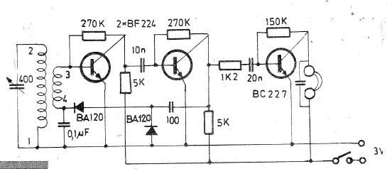
Oscillating circuits (coils) are constructed on a ferrite bar. For long wave reception, winding "1-2" consists of 135 turns, while winding "3-4" has 20 turns. For medium wave reception, winding "1-2" has 75 turns, and winding "3-4" has 7...
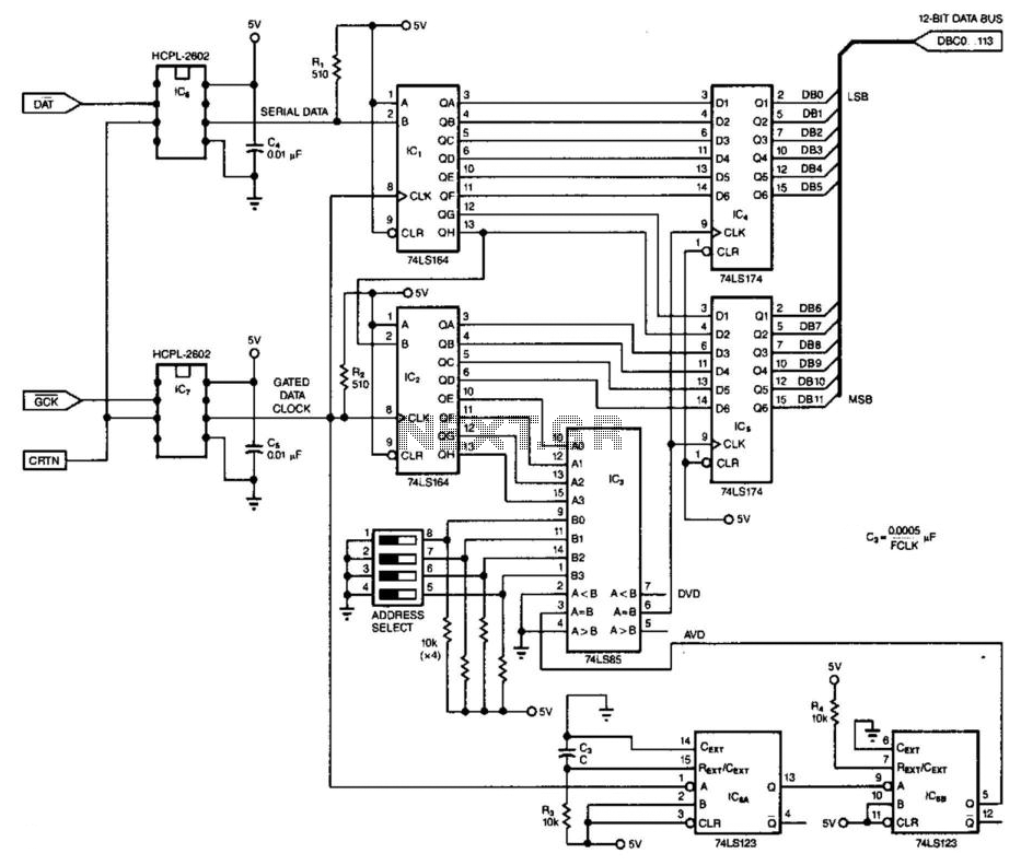
This 3-wire receiver verifies the initial four data bits of 16 received bits against a predetermined address. If the two match, the remaining 12 bits are stored in two 6-bit flip-flop registers. The design can utilize either CMOS or...
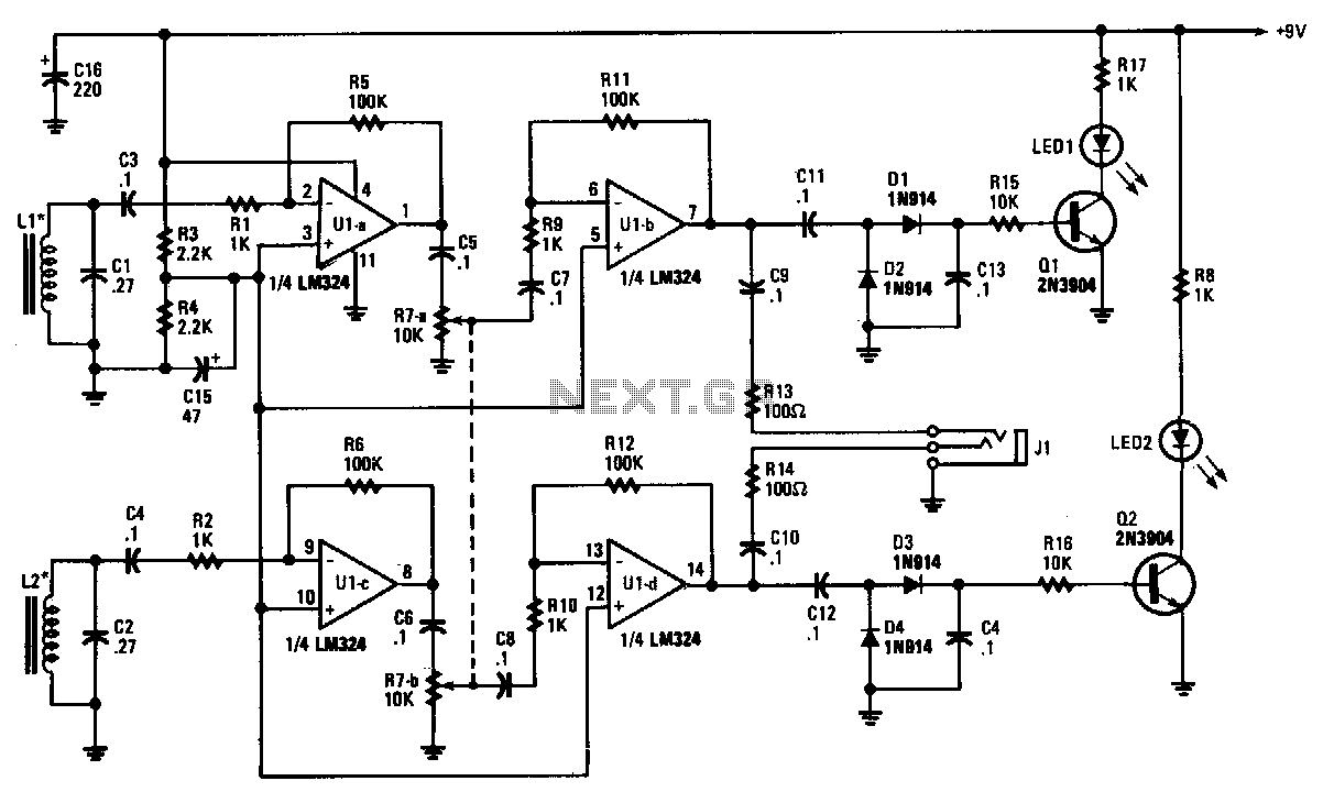
The tracer receiver is a stereo audio amplifier and detector circuit that operates at a frequency close to 1 kHz. Inductors L1 and L2 are hand-wound coils, each consisting of 200 turns of #26 wire on 2-inch ferrite cores,...
This two-transistor AM radio circuit is also referred to as a "mini-radio." It utilizes only two transistors and a few passive components, which makes it very easy to construct. The two-transistor AM radio circuit operates by utilizing a simple design...
This AM/FM antenna booster circuit amplifies the broadband signal from the antenna. This antenna booster is designed to work for FM, AM, and SW receivers. The AM/FM antenna booster circuit is an essential component for enhancing radio reception across...
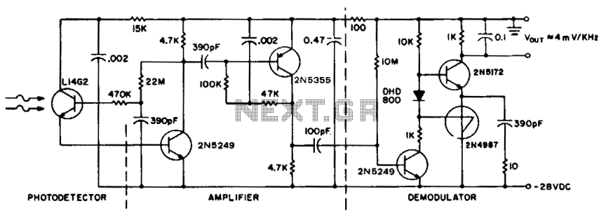
To achieve maximum range, the receiver should be constructed similarly to a radio receiver front end, as the signals received will exhibit comparable frequency components and amplitudes of the photodiode current. The primary limitation on the receiver's performance is...