
Pseudorandom Simulated Flicker Sequencer
The described circuit functions as an innovative lighting control system that utilizes a pseudorandom sequencer to create flickering light effects. The primary components include an oscillator and a sequencer, which work in tandem to generate a unique serial bit stream. This bit stream is characterized by a period of 32,767 bits, ensuring a long cycle before the pattern repeats, thus enhancing the unpredictability of the light output.
The feedback mechanism implemented through stages 14 and 15 allows for dynamic adjustment of the sequencer's operation, ensuring that the output remains varied. The integration of the RC network serves a critical role during the power-up phase, delivering a pulse that prevents the sequencer from entering a non-functional state. This design consideration is vital for reliable operation, particularly in environments where power fluctuations may occur.
The XOR gates (IC4A and IC4B) introduce additional complexity to the output pattern, further enhancing the realism of the simulated flame effects. By scrambling the output, these gates contribute to a more natural flickering effect, making the lighting more visually appealing.
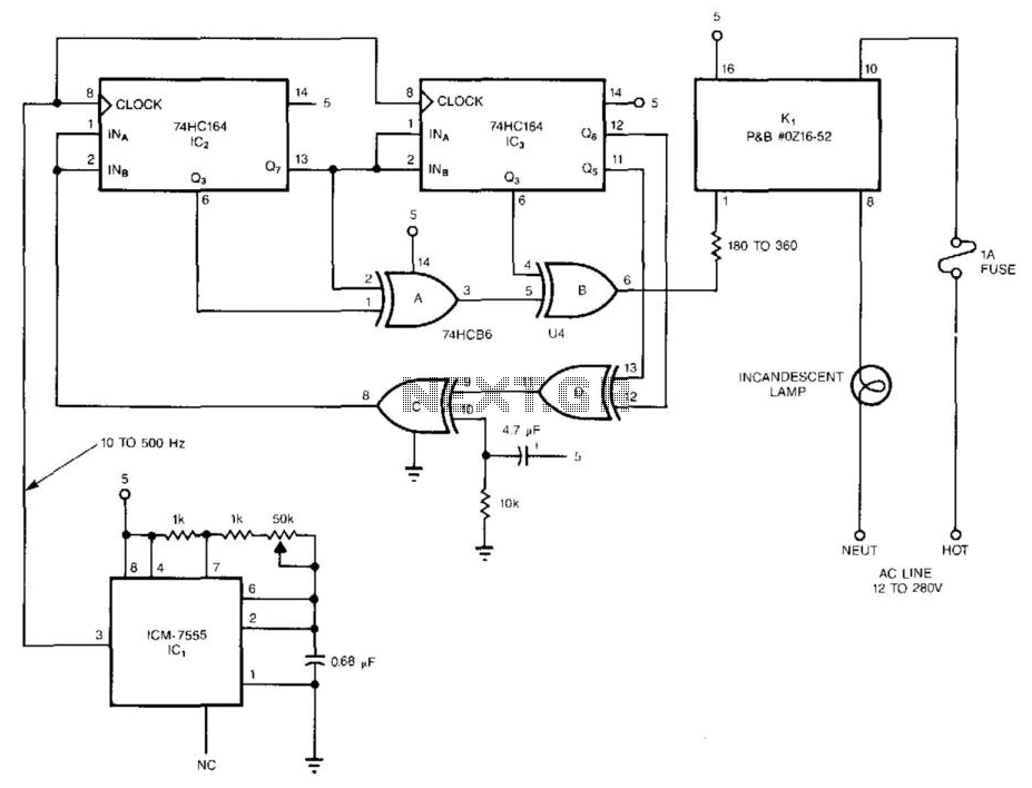
The solid-state relay operates with zero-voltage switching, which minimizes electrical noise and enhances the lifespan of both the relay and the connected lighting elements. Capable of handling loads up to 1 A across a wide voltage range (12 to 280 Vac), this relay is suitable for various applications, from decorative lighting to more significant installations. The use of multiple circuits can create a more extensive lighting array, intensifying the effect and providing a versatile solution for ambient lighting needs. The pseudorandom sequencer drives a solid-state relay. If you power a low-wattage lamp from the re lay, the lamp will appear to flicker like a candle"s flame in the wind; using higher-wattage lamps allows you to simulate the blaze of a fireplace or campfire. You can enhance the effect by using three or more such circuits to power an array of lamps. The circuit comprises an oscillator, IC1, and a 15-stage, pseudorandom sequencer, IC2-4. The sequencer produces a serial bit stream that repeats only every 32 767 bits. Feedback from the sequencer"s stages 14 and 15 go through IC4D and back to the serial input of IC2. Notice the RC network that feeds IC4C; the network feeds a positive pulse into the sequencer to ensure that it won"t get stuck with all zeros at power-up.
The leftover XOR gates IC4A and IC4B further scramble the pattern. The serial stream from IC4B drives a solid-state relay that features zero-voltage switching and can handle loads as high as 1 A at 12 to 280 Vac. 🔗 External reference
Related Circuits
All LED negatives are connected to the "COM" pad, then through a 220 Ohm resistor to ground. There is no need for additional current limiting resistors, even with supply voltages up to 16 volts. The described circuit employs a simple...
There are many posts on Instructables detailing how to create a flickering LED candle. This version of the project requires several components. The flickering LED candle project aims to simulate the warm glow and flicker of a real candle using...
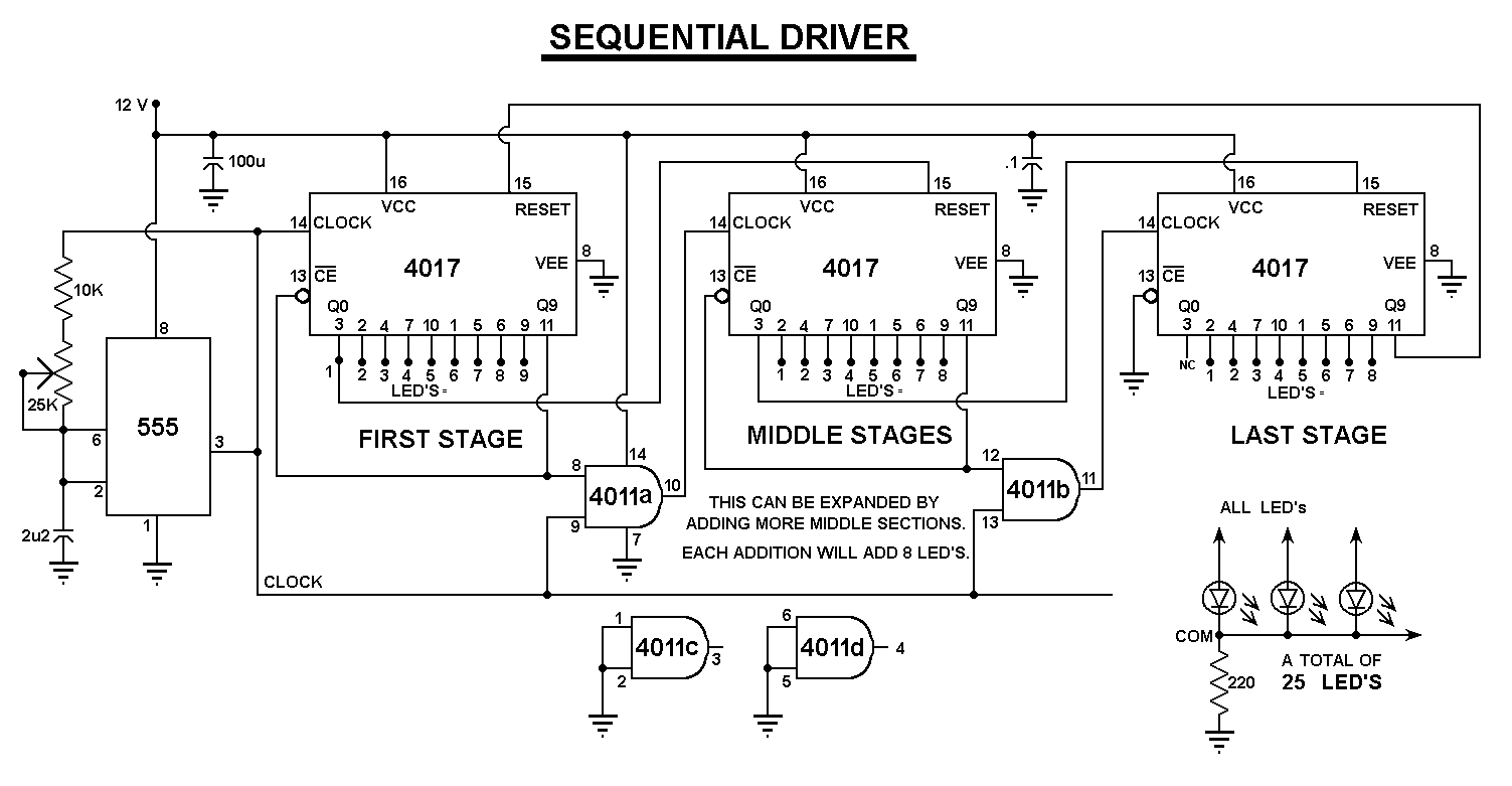
The purpose of this circuit is to create a ring in which LEDs or lamps illuminate sequentially. Its main feature is high versatility; a loop containing any number of LEDs or lamps can be built, as each illuminating device...
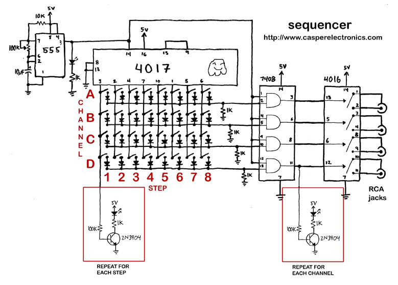
The output of the 4017 has a 100% duty cycle, meaning that if step one and step two are activated, they will overlap, resulting in a step that lasts for two cycles. In contrast, the output of the 555...
A 10-light LED bar graph is desired, where the LEDs light up sequentially until all are lit, then cycle back down until all are off. The LM3914 - Dot/Bar Display Driver is a simpler analog solution that operates in...
This is a sequencer circuit. Power to the logic portion of the circuit is provided by a standard commercial "wall-wart" power adapter supplying 6 VDC. The 555 timer IC generates the pulse train that drives the chase, with timing...