
88-108MHz FM Transmitter

The FM transmitter circuit operates in the VHF band, specifically designed for frequencies between 88 MHz and 108 MHz, which is the standard FM broadcast band. The 1W output power indicates that this transmitter can be used for short-range broadcasting applications, making it suitable for hobbyists and educational projects.
The circuit typically includes several key components: an oscillator, modulator, amplifier, and various passive components such as capacitors and resistors. The oscillator generates the carrier wave at the desired frequency, while the modulator combines the audio input signal with the carrier wave, encoding the audio information onto the carrier for transmission.
Capacitors play a crucial role in filtering and tuning the circuit. They are used to stabilize the frequency of the oscillator and to couple signals between different stages of the transmitter. The choice of capacitor values affects the overall performance, including frequency stability and bandwidth.
The amplifier stage boosts the modulated signal to the required power level for transmission. It is important to ensure that the amplifier can handle the load presented by the antenna, which is typically a simple dipole or monopole design for FM transmission.
Overall, this FM transmitter circuit is a practical example of analog communication principles, allowing for the transmission of audio signals over a designated frequency band. Proper consideration of component selection and circuit layout is essential for achieving optimal performance and compliance with regulatory standards for RF transmission.The following circuit shows about 88-108MHz FM Transmitter Circuit Diagram. Features: 1W transmitter Tetsuo style. Component: Capacitor, .. 🔗 External reference
Related Circuits
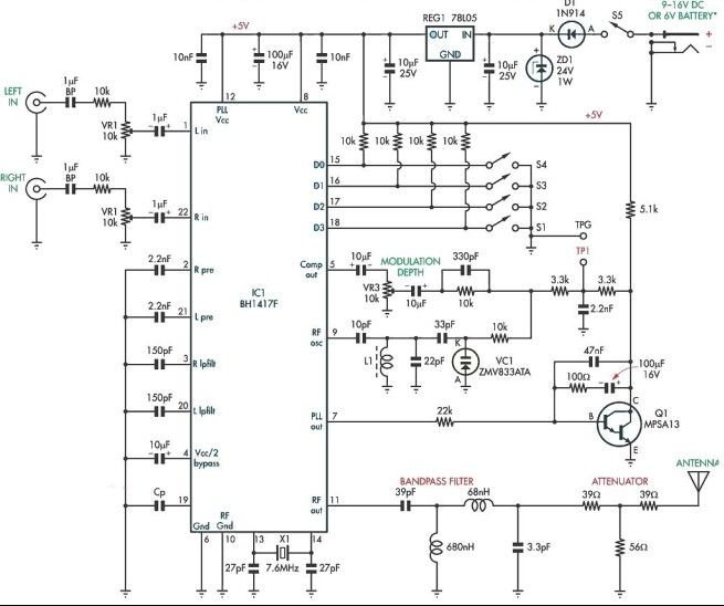
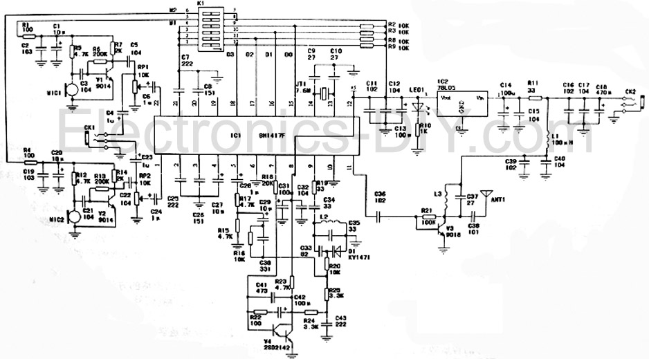
This stereo FM modulator circuit utilizes the BH1417F FM stereo transmitter IC, which includes a stereo modulator for generating stereo composite signals and an FM transmitter for broadcasting an FM signal wirelessly. The stereo modulator produces a composite signal...
L1 is 0.112uH (this tunes to the middle of the FM band, 98 MHz, with VC1 at its centre value of 33pF). L1 is 5 turns of 22 swg enamelled copper wire close-wound on a 5mm (3/16") diameter former....
This low-cost short-wave transmitter is tunable from 10 to 15 MHz using a ½J gang condenser VC1, which sets the carrier frequency in conjunction with inductor L1. Frequency trimming is achieved with VC2. The carrier signal is amplified by...
Maxim has introduced a series of five integrated oscillator building blocks in the MAX260x series, covering a frequency range of 45 to 650 MHz. The MAX2606 is designed for the VHF band, allowing frequency variation of approximately ±3 MHz...
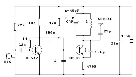
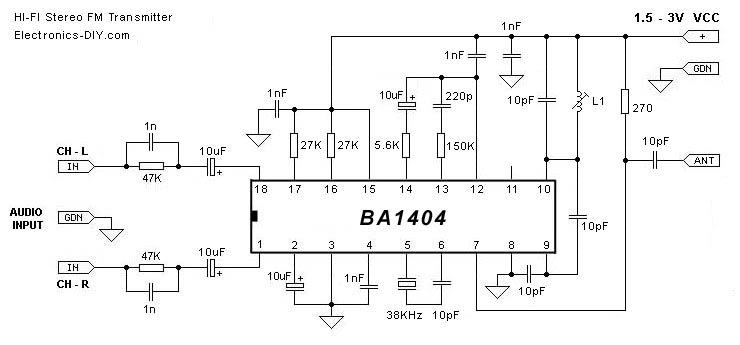
This FM transmitter circuit is very simple and has an acceptable transmission range. The signal transmitted from this FM transmitter circuit can be received at almost 300 meters in open air. The circuit requires a 3-volt operating voltage and...
This is a high-fidelity stereo PLL FM transmitter designed for various audio sources including computers, sound cards, game consoles, CDs, DVDs, MP3 players, and stereo mixers. The board features two microphone amplifiers, enabling high-fidelity FM stereo radio transmission when...