
2.5V voltage regulator circuit

The 2.5V voltage regulator circuit is designed to maintain a stable output voltage of 2.5V from a higher input voltage, specifically 5V. The RT9202 integrated circuit (IC) plays a crucial role as the control core of this regulation process. It utilizes pulse-width modulation (PWM) to adjust the output voltage dynamically, ensuring that variations in load conditions do not affect the regulated voltage.
The circuit typically includes input and output capacitors to stabilize the voltage levels and minimize ripple. The input capacitor (C1) is placed close to the input pin of the RT9202 to filter out any high-frequency noise from the power supply. The output capacitor (C2) is similarly positioned to smooth the output voltage and enhance transient response.
Additionally, the circuit may incorporate resistors for setting the output voltage and feedback mechanisms that allow the RT9202 to monitor the output voltage continuously. This feedback loop is essential for maintaining the desired voltage level under varying load conditions. The design also considers thermal management, as the regulator may dissipate heat during operation; therefore, proper heat sinking or thermal pads might be necessary to ensure reliability.
In summary, this voltage regulator circuit is an essential component of computer motherboards, ensuring that sensitive electronic components receive a stable and reliable 2.5V supply from a 5V input, thereby enhancing the overall performance and stability of the system.2.5V voltage regulator circuit Shows the computers motherboard in 2.V voltage regulator circuit, the oscillation circuit switch IC RT9202 control core chip, will become +2.V po wer supply voltage 5v output voltage chip conscious end is + 12V power supply.
Related Circuits
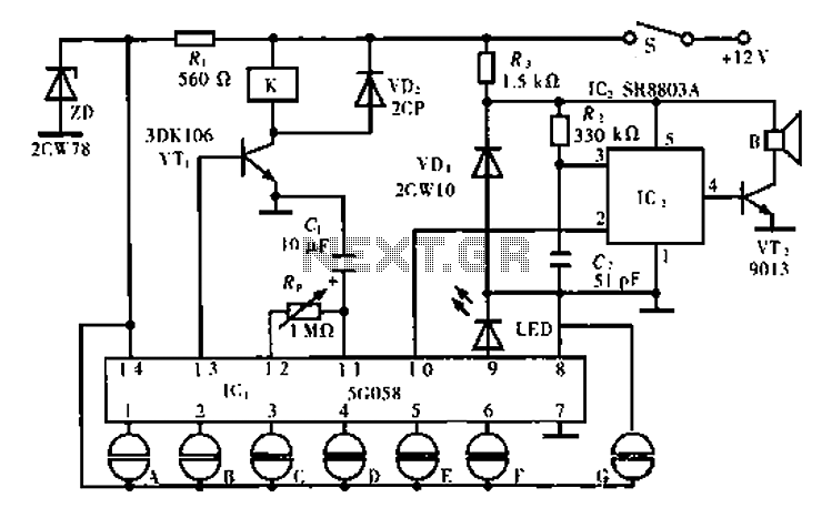
The circuit operates using an ASIC lock IC, specifically the 5C058. Pins 1 to 6 are connected outside the key switch to the positive power supply, representing six valid key inputs. To unlock, keys A through F must be...
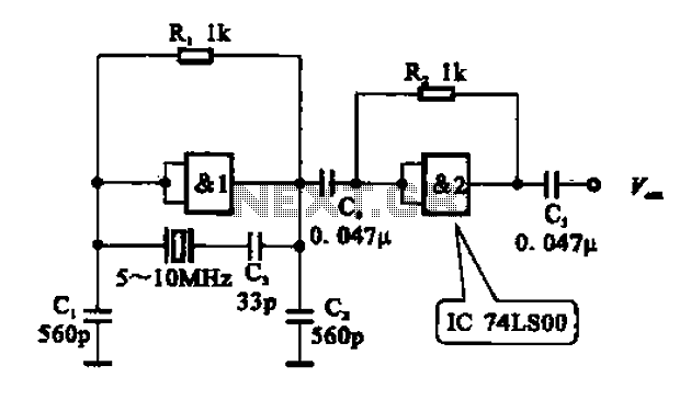
A crystal oscillator circuit comprises various gates as illustrated in the provided figures. Figure (A) represents a crystal oscillator circuit operating at 1 MHz, while figure (B) depicts a 20 MHz crystal oscillator circuit. Figure (C) shows a variable...
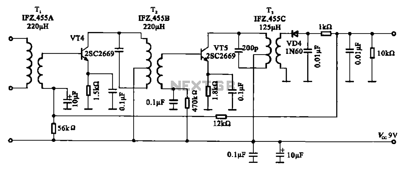
AM radio shows the IF amplifier and detector circuit. The mixer receives the intermediate frequency output signal from the transformer after the device. This signal is applied to the base of the intermediate frequency transistor VT4. The collector load...
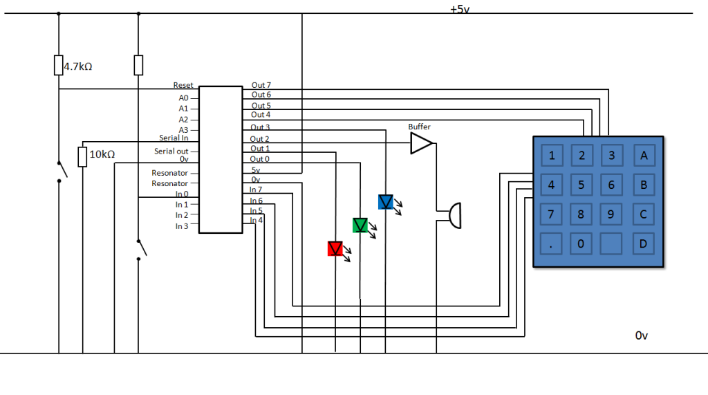
A keypad lock is being developed using a PIC microcontroller and a passive keypad with 8 pins, consisting of 4 input and 4 output pins. Each input pin corresponds to a row of numbers on a 4x4 keypad, while...
This circuit is a melody generator circuit diagram controlled by the UM66 IC. The UM66 is a CMOS IC designed for applications such as call bells, telephones, and toys. It features a built-in ROM programmed to play music and...
This microphone preamplifier utilizes the low-noise integrated circuit (IC) uA739. It serves as a practical example of designing an effective preamplifier for dynamic microphones. The IC contains two identical integrated preamplifier circuits, with the second preamp functioning in the...