
lm317 universal battery charger circuit

The universal battery charger circuit is designed for versatility and efficiency in charging various types of batteries. The LM317 voltage regulator is pivotal in providing a stable output voltage that can be fine-tuned according to the specific requirements of the battery being charged. The inclusion of the operational amplifier enhances the circuit's ability to monitor and adjust the charging process, ensuring optimal performance and battery longevity.
The 2N3055 transistors function as power amplifiers, allowing the circuit to handle higher current loads while maintaining regulation. Their configuration as series regulators enables precise control over the output voltage and current, essential for safe charging practices. The adjustment potentiometer R9 allows users to set the desired output voltage easily, accommodating different battery chemistries and configurations.
The current-sampling resistor R8 plays a critical role in feedback regulation. It provides a real-time measurement of the charging current, which is essential for preventing overcharging and ensuring that the battery is charged efficiently. The operational amplifier's comparator function continuously monitors the voltage across R8, allowing the circuit to dynamically adjust the output as needed.
Overall, this universal battery charger circuit is a robust solution for battery charging applications, combining simplicity, effectiveness, and adaptability to various battery types and configurations. It is suitable for hobbyists and professionals alike, providing a reliable method for maintaining battery health and performance.This universal battery charger is based on LM317 and has an adjustable regulated output voltage and also has an adjustable constant-current charging circuit that makes it suitable to use for charging most NiCad batteries and some other types of batteries. This LM317 universal battery charger can charge a single cell or a number of series-connecte d cells up to a maximum voltage of 18 V. This universal battery charger circuit use just some common electronic components like LM317 regulator, operational amplifier and some 2n3055 power transistors. 2n3055 power transistors Q1 and Q2 are connected as series regulators to control the battery charger`s out ¬put voltage and charge-current rate.
The LM317 used as an adjustable voltage regulator supplies the drive signal to the bases of power transistors Q1 and Q2. By turning the potentiometer R9 the output-voltage level will be modified. A current-sampling resistor, R8 (a 0. 1-fi, 5-W unit), connected between the negative output lead and circuit ground. As the charging voltage across the battery begins to drop, the current through R8 decreases, then the voltage feeding pin 5 of U3 decreases, and the comparator output follows, turning Q3 back off, which completes the signal`s circular path to regulate the battery`s charging current.
🔗 External reference
Related Circuits
The circuit diagram presented illustrates the MC14093B Fluid Level Sensor Circuit. It is characterized by its compact and simple design, utilizing a single-chip configuration suitable for a wide range of applications. The MC14093B is a CMOS quad two-input NAND gate...
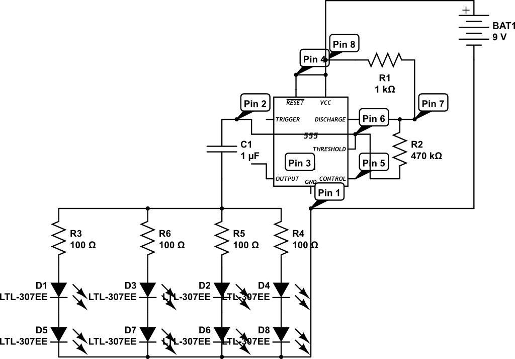
LEDs are rated for a continuous current of only 30 mA, while this circuit operates them at approximately 50 mA. Although this is acceptable for low duty cycles with short pulses, the intended design has a high duty cycle....
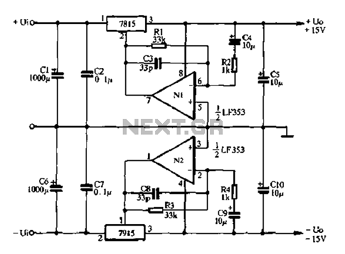
15V active servo power supply circuit The 15V active servo power supply circuit is designed to provide a stable and regulated output voltage of 15 volts, suitable for powering servo motors and other related devices. This circuit typically employs a...
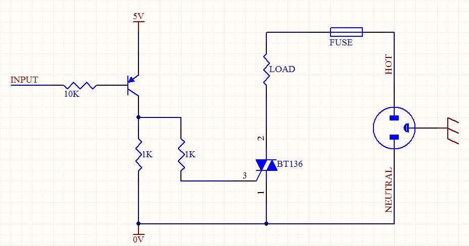
A circuit was designed to function as a light dimmer, utilizing a BT136 SCR and an MOC3022 optocoupler. However, the circuit did not operate as intended. The circuit aims to control the brightness of a light source through phase control...
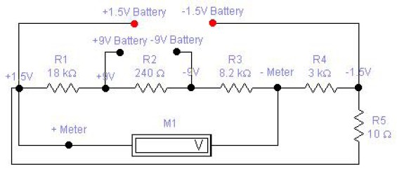
The circuit diagram of a DC battery tester designed by Matthew B. This circuit can measure DC batteries ranging from 1.5V to 9V. Component Parts List: R1 = 18K Ohm, R2 = 240 Ohm, R3 = 8.2K Ohm, R4...
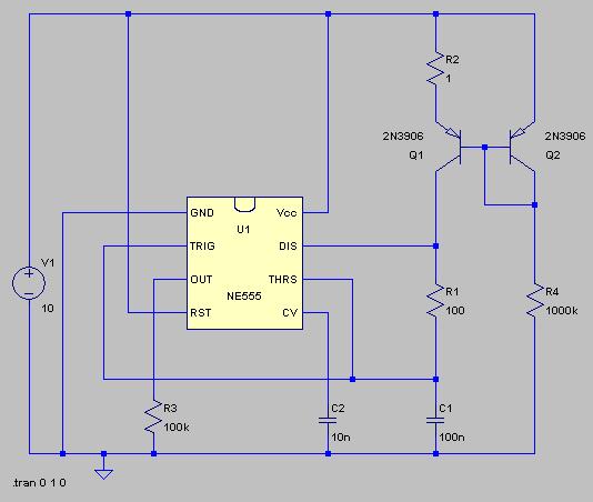
The typical BPM range for music is between 40 and 240 BPM, corresponding to periods of 1500 ms and 200 ms, respectively. A BPM of 120 equates to a period of 500 ms. The circuit requires a resistor R4...