
200w atx power supply circuit

The 200W ATX power supply circuit serves as a robust source of regulated DC power, commonly utilized in computer applications. It converts the AC mains voltage to various lower DC voltages required by computer components. The circuit typically includes a transformer, rectifier, filter capacitors, and a voltage regulation stage, ensuring stable output across varying loads.
In conjunction with the power supply circuit, the battery monitor circuit provides a means to monitor battery voltage levels effectively. The astable multivibrator configuration formed by transistors Q1 and Q2 generates a square wave output, which is used to drive an LED indicator. The frequency of the LED's flashing serves as a visual cue for the battery's state.
The operational range of the battery monitor circuit, capable of functioning between 6V and 12V, allows it to be versatile for different battery types. The resistor R4 plays a critical role in setting the threshold voltage at which the LED ceases to flash. As the battery voltage rises above this threshold, the flashing frequency diminishes, indicating a healthy battery state. Conversely, when the voltage falls below this threshold, diode D1 is activated, turning the LED off, which serves as a warning for low battery conditions.
This dual-function circuit setup enhances the reliability and usability of electronic systems by providing both stable power supply and effective battery monitoring, crucial for maintaining operational efficiency in various applications.200W ATX Power Supply Circuit power supply. Go to that page to read the explanation about above power supply related circuit diagram. Here is asimple battery monitor circuitin which theLEDwillcontinueflashinguntil battery voltageis above thelevel. TransistorsQ1andQ2arewiredasan astable multivibratorcircuit . Thisflashingbatterymonitorcircuitcan operatefroma variety ofvoltagesfrom6Vto12V. Thevoltagelevelat whichanLEDstopsflashingcan be setby adjustingR4. When thea presetbatteryvoltagereachesthresholdflashingfrequencydecreasesandwhenthe voltagedrops belowthe threshold ofthe diodeD1LEDturnsOFF. This is usedtocompensate for changesinvoltage ofthe baseemitterQ1due the. 🔗 External reference
Related Circuits
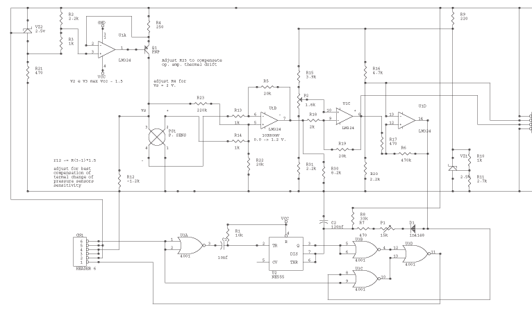
The circuit is powered by the receiver's pack, the current drain is low, especially if compared to drain of servos. U1a VZ2 and Q1 are the current source of the sensor. VZ2 is temperature compensated; use the listed component...
The following circuit illustrates a Power Amplifier Circuit Diagram utilizing a 2N3055 transistor. Features include a 500-ohm current and an optimal voltage of 50V. The power amplifier circuit based on the 2N3055 transistor is designed to deliver significant output power,...
The image depicts an ultrasonic liquid level indicator circuit. This circuit consists of an ultrasonic transmitter circuit and a receiver circuit. The ultrasonic transmitter circuit includes a 555 timer, resistor R1, variable resistor W1, capacitor C1, and the ultrasonic...
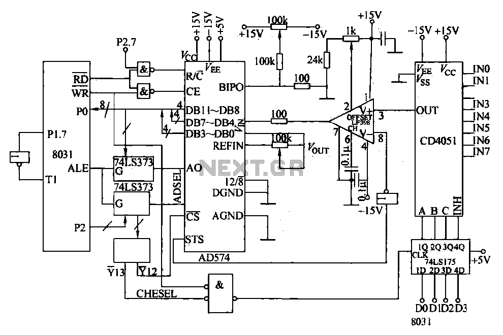
Converters and data sampling: A 12-bit A/D converter, AD574, is interfaced with an 8031 microcontroller circuit. Parameters are measured by a multi-way switch after a CD4051 strobe signal is sent to the sample/hold input device. The selection of the...
Since I have provided the schematic for John L Linsley-Hood's Class-A amplifier, I felt that some readers may wish to experiment with the concept. Unfortunately, a very low ripple power supply is needed for all Class-A amps, and the...
If the offset value exceeds 5mV, adjust this value by experimenting with resistors, starting with 220K, connected from test point Z (the junction of R22 and R23) to +V if there is a negative voltage, or to -V if...