
stereo channel circuit diagram

This circuit is designed to facilitate seamless audio source selection in stereo systems by automatically detecting audio signals and switching between multiple inputs. The core functionality revolves around the use of analog switches (CD4066) that are controlled by a ring counter (CD4017), ensuring that only one channel is active at any time. The NE555 timer is configured in astable mode to provide a continuous clock signal to the ring counter, enabling systematic channel selection.
The circuit's design allows for both automatic and manual channel selection, enhancing user experience. The inclusion of adjustable threshold levels for audio detection ensures compatibility with various audio sources, allowing for fine-tuning based on the specific requirements of the audio environment. The use of LEDs for visual feedback on the selected channel improves usability, providing clear indication of which source is currently active.
In applications where multiple audio sources are utilized, this circuit can significantly simplify the process of managing input signals, reducing the need for manual intervention and ensuring that audio playback is uninterrupted. With the potential for expansion to accommodate additional channels, this design offers flexibility for various stereo system configurations, making it a valuable addition to any audio setup.The add-on circuit presented here is useful for stereo systems. This circuit has provision for connecting stereo outputs from four different sources/channels as inputs and only one of them is selected/connected to the output at any one time. When power supply is turned on`, channel A (AR and AL) is selected. If no audio is present in channel A, th e circuit waits for some time and then selects the next channel (channel B). This search operation continues until it detects audio signal in one of the channels. The inter-channel wait or delay time can be adjusted with the help of preset VR1. If still longer time is needed, one may replace capacitor C1 with a capacitor of higher value. Suppose channel A is connected to a tape recorder and channel B is connected to a radio receiver. If initially channel A is selected, the audio from the tape recorder will be present at the output. After the tape is played completely, or if there is sufficient pause between consecutive recordings, the circuit automatically switches over to the output from the radio receiver. To manually skip over from one (selected) active channel to another (non-selected) active channel, simply push the skip switch (S1) momentarily once or more, until the desired channel input gets selected.
The selected channel (A, B, C, or D) is indicated by the glowing of corresponding LED (LED11, LED12, LED13, or LED14 respectively). IC CD4066 contains four analogue switches. These switches are connected to four separate channels. For stereo operation, two similar CD4066 ICs are used as shown in the circuit. These analogue switches are controlled by IC CD4017 outputs. CD4017 is a 10-bit ring counter IC. Since only one of its outputs is high at any instant, only one switch will be closed at a time. IC CD4017 is configured as a 4-bit ring counter by connecting the fifth output Q4 (pin 10) to the reset pin.
Capacitor C5 in conjunction with resistor R6 forms a power-on-reset circuit for IC2, so that on initial switching on` of the power supply, output Q0 (pin 3) is always high`. The clock signal to CD4017 is provided by IC1 (NE555) which acts as an astable multivibrator when transistor T1 is in cut- off state.
IC5 (KA2281) is used here for not only indicating the audio levels of the selected stereo channel, but also for forward biasing transistor T1. As soon as a specific threshold audio level is detected in a selected channel, pin 7 and/or pin 10 of IC5 goes low`.
This low level is coupled to the base of transistor T1, through diode-resistor combination of D2-R1/D3-R22. As a result, transistor T1 conducts and causes output of IC1 to remain low` (disabled) as long as the selected channel output exceeds the preset audio threshold level.
Presets VR2 and VR3 have been included for adjustment of individual audio threshold levels of left and right stereo channels, as desired. Once the multivibrator action of IC1 is disabled, output of IC2 does not change further. Hence, searching through the channels continues until it receives an audio signal exceeding the preset threshold value.
The skip switch S1 is used to skip a channel even if audio is present in the selected channel. The number of channels can be easily extended up to ten, by using additional 4066 ICs. Disclaimer: All the information present on this site are for personal use only. No commercial use is permitted without the prior permission from authors of this website. All content on this site is provided as is and without any guarantee on any kind, implied or otherwise. We cannot be held responsible for any errors, omissions, or damages arising out of use of information available on this web site.
The content in this site may contain COPYRIGHTED information and should not be reproduced in any way without prior permission from the authors. 🔗 External reference
Related Circuits
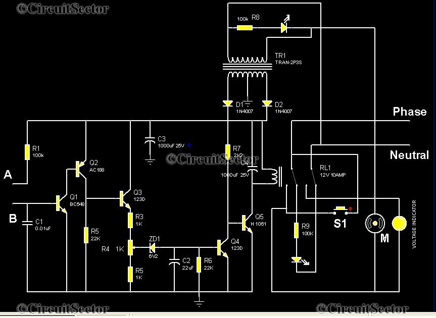
This is an automatic water tank controller designed to manage the operation of a water pump using a 12V 10A relay. When the water level in the tank creates a short circuit between points A and B in the...
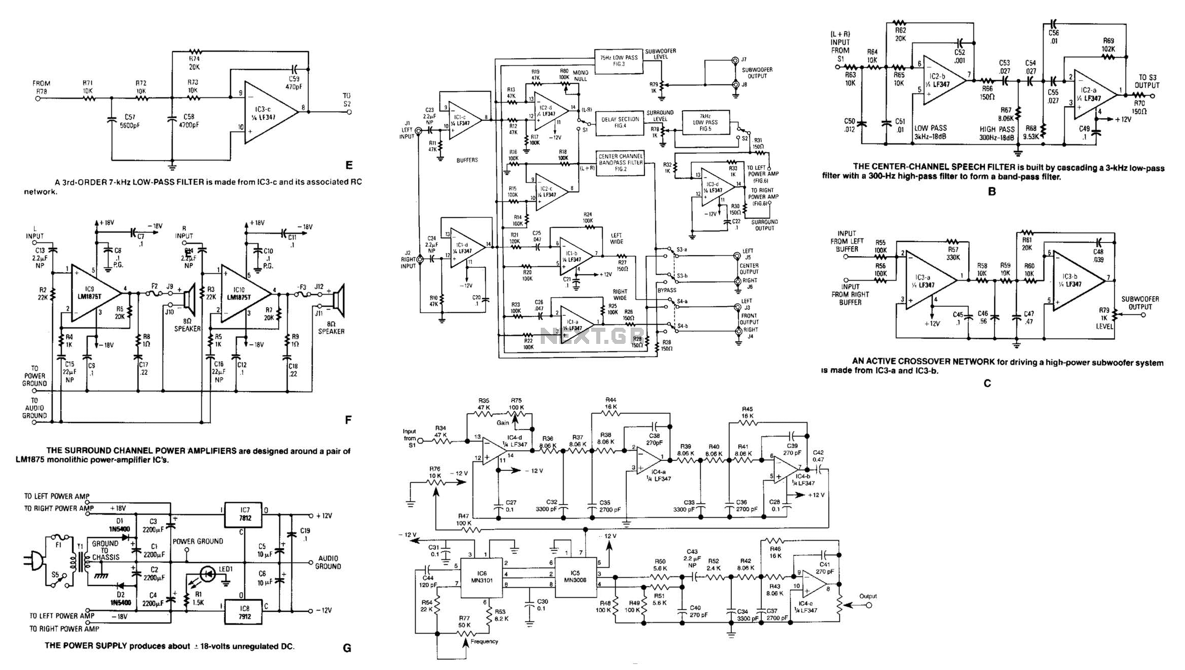
Referring to the simplified schematic in A, the audio frequency generator (AFG) consists of 10 relatively simple circuit elements. IC1-c and IC1-d are configured as unity-gain non-inverting buffer amplifiers. The summing amplifier, IC2-c, combines equal amounts of the left...
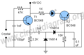
A highly beneficial project involving a crystal tester circuit, also known as an xtal tester circuit, constructed with only a few components. The circuit forms an oscillator that will only oscillate if the crystal under test is functioning properly....
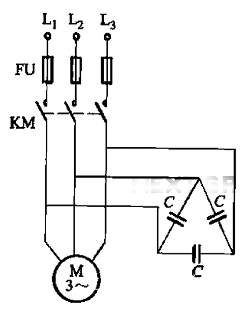
Asynchronous motor reactive power compensation involves directly connecting a capacitor to the stator windings of the asynchronous motor to enhance its power factor. This method is particularly effective for synchronous motors, as it reduces energy consumption related to reactive...
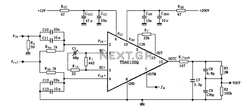
Feedback has indicated that the TDA6120Q test circuit, as shown in the figure, utilizes an input signal (Vi) composed of resistors Ra and capacitors C10 and C11, which are fed into the TDA6120Q at pins 2, 3, and 4....
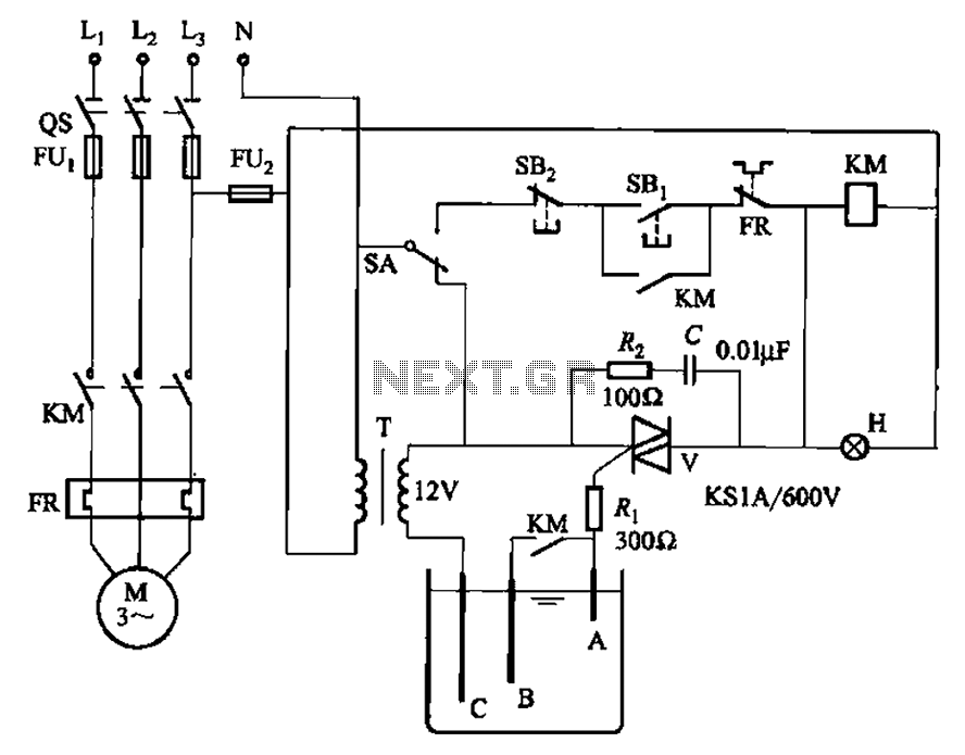
Bidirectional thyristor control manages the trigger voltage output from the step-down transformer at 12V when the water activates the electrodes. It is part of a drawable circuit that regulates the level. The circuit includes a current-limiting resistor (Ri) to...