
28V DC To 5V DC Switch-Mode Converter (Regulator)
")
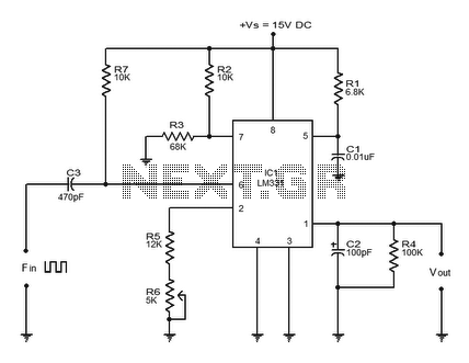
The 28VDC to 5VDC switching converter circuit operates by converting a higher voltage direct current (DC) input into a lower voltage DC output with increased efficiency. The circuit typically employs a power switch, usually a transistor, which rapidly turns on and off to control the energy transfer from the input to the output. This switching action allows the circuit to maintain a stable output voltage while minimizing energy loss, a significant advantage over linear regulators which dissipate excess voltage as heat.
Key components of the circuit include an inductor, a diode, and capacitors. The inductor stores energy when the switch is closed and releases it to the output when the switch is open. The diode prevents backflow of current and ensures that the energy flows in the correct direction. Input and output capacitors are used to smooth out voltage fluctuations, providing a stable output voltage.
The efficiency of this switching converter can be further enhanced by employing techniques such as pulse-width modulation (PWM) to control the duty cycle of the switch, optimizing the energy transfer process. Additionally, feedback mechanisms may be implemented to monitor the output voltage and adjust the switching operation accordingly, ensuring consistent performance under varying load conditions.
Overall, this 28VDC to 5VDC switching converter circuit is an effective solution for applications requiring efficient power conversion, making it suitable for powering low-voltage devices from higher voltage sources.This is a 28VDC to 5VDC switching converter circuit. As a switch-mode voltage regulator, this circuit gives higher efficiency than linear regulator type.. 🔗 External reference
Related Circuits
The TLD 5085EJ is a smart LED buck converter featuring an integrated power switch, designed to drive a load current of up to 1.8A with excellent line and load regulation. This device is specifically intended for stepping down input...
This circuit diagram illustrates the design of a straightforward AC voltage converter that transforms 240V AC power into 110V AC. The circuit can effectively be utilized to power electrical devices that necessitate a supply voltage of 110V. The AC voltage...
The successive approximation Analog to Digital Converter (ADC) is one of the most common types of ADC. It requires few components and is straightforward to operate. Additionally, it always takes the same amount of time to calculate the result....
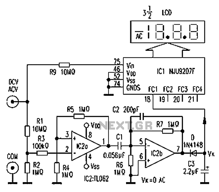
The circuit depicted in the figure illustrates an automatic AC/DC converter for a digital multimeter. Typically, standard digital multimeters require manual intervention to switch between AC and DC measurements. The new DT860D digital multimeter utilizes the NJU9207F automatic range...
The LM331 is a precision voltage-to-frequency converter developed by National Semiconductors. This integrated circuit (IC) has various applications, including analog-to-digital conversion, long-term integration, voltage-to-frequency conversion, and frequency-to-voltage conversion. Its wide dynamic range and excellent linearity make it suitable for...
This type of converter is used to convert analog voltage to its corresponding digital output. The function of the analog-to-digital converter is exactly opposite to that of a digital-to-analog converter. Like a digital-to-analog converter, an analog-to-digital converter is also...