
2N2222 Transistor For Three Phase Auto Changer

The Three Phase Auto Changer Circuit is designed to automatically switch between different phases in a three-phase power system, ensuring balanced load distribution and enhanced operational efficiency. The core component of this circuit is the 2N2222 transistor, a versatile NPN bipolar junction transistor widely used for switching applications due to its reliability and performance characteristics.
The circuit typically consists of a transformer that steps down the voltage to a manageable level suitable for the control circuitry. The transformer is essential for isolating the control circuit from the high voltage side, providing safety and stability. The primary winding of the transformer is connected to the three-phase supply, while the secondary winding provides the necessary voltage to drive the control logic.
The 2N2222 transistor acts as a switching element in this circuit. It is configured in a manner that allows it to control the flow of current to the load based on the phase input it receives. When a specific phase is detected, the transistor is turned on, allowing current to flow through the load connected to that phase. This automatic switching mechanism helps in maintaining the operational efficiency of three-phase systems by optimizing the load on each phase.
Additional components may include resistors and capacitors that are strategically placed to filter noise and stabilize the operation of the transistor. These components ensure that the circuit operates smoothly without interference from voltage spikes or fluctuations in the supply.
Overall, the Three Phase Auto Changer Circuit using the 2N2222 transistor is an effective solution for managing three-phase power systems, facilitating automatic phase switching, and improving load management in various industrial and commercial applications.The following circuit shows about Three Phase Auto Changer Circuit Diagram. This circuit using the 2N2222 Transistor. Features: transformer with .. 🔗 External reference
Related Circuits
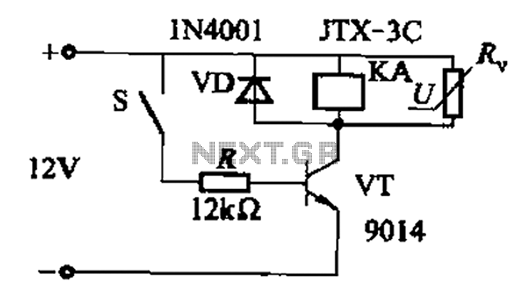
In a concrete circuit relay application, the transistor VT functions as a high-speed, high-voltage switch. The voltage requirement for switching is 5 to 10 times the rated voltage of the solenoid valve. The circuit is designed for a fast...
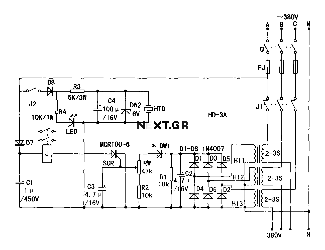
A current transformer H11-3 needs to be constructed. Select a transformer core with a minimum power rating of 2W for the first secondary winding. Use enameled wire with a diameter of 0.12 mm and wind approximately 1000 turns. The...

Phase-shift oscillator. An oscillator in which a network has a phase shift of 180 degrees. A phase-shift oscillator is a type of electronic oscillator that generates a sinusoidal output signal. It typically consists of an amplifier and a phase-shifting network...
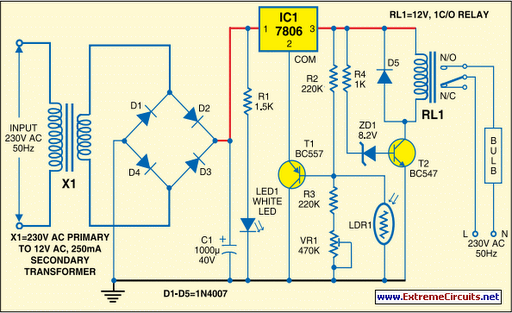
Voltage regulator ICs (78xx series) deliver a stable output voltage despite a fluctuating input supply when the common terminal is grounded. Any voltage above zero volts (ground) connected to the common terminal is added to the output voltage, meaning...
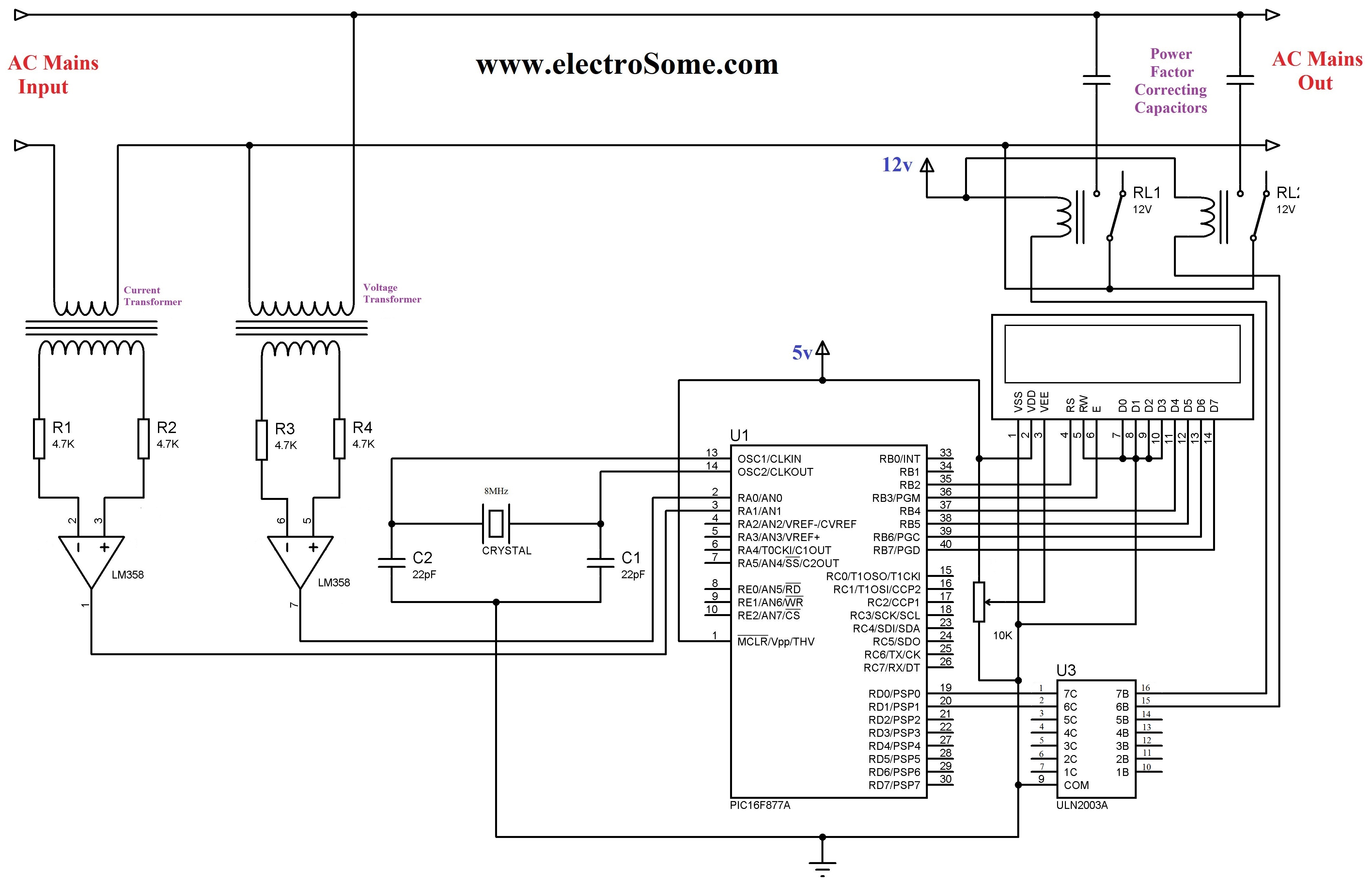
The 230 V, 50 Hz supply is stepped down using a voltage transformer, while a current transformer is utilized to extract the current waveforms. The output of the voltage transformer corresponds to the voltage across the load, and the...
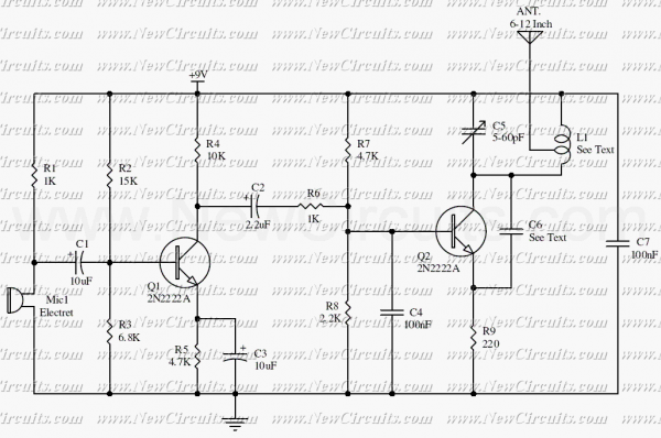
This circuit is a simple two transistor (2N2222) FM transmitter. No license is required for this transmitter according to FCC regulations regarding wireless microphones. If powered by a 9-volt battery and used with an antenna no longer than 12...