
3-3.5 Watt FM Transmitter
The 3-3.5 Watt FM transmitter circuit operates within the frequency range of 90 to 110 MHz, making it suitable for various broadcasting applications. The circuit typically comprises several key components, including an oscillator, modulator, amplifier, and antenna.
The oscillator generates a carrier frequency within the specified range, ensuring that the transmitter can operate effectively across the FM band. The modulator then superimposes the audio signal onto the carrier wave, allowing for the transmission of audio content.
An RF amplifier is crucial for boosting the power of the modulated signal to the desired output level of 3 to 3.5 watts. This amplification is critical for ensuring that the signal can effectively propagate over the intended distance, providing clear reception for FM radios within range.
To enhance stability, the circuit may incorporate feedback mechanisms or frequency stabilization techniques, which help maintain the carrier frequency despite variations in temperature or component tolerances. Proper component selection, including capacitors, inductors, and transistors, is essential for achieving optimal performance and reliability.
The final output is transmitted through an antenna designed to match the operating frequency, ensuring efficient radiation of the RF signal. This transmitter design is commonly used in educational projects, hobbyist applications, and low-power broadcasting scenarios, offering a practical solution for those looking to explore FM transmission technology.3-3.5 Watt FM Transmitter. This is the schematic for an FM transmitter with 3 to 3.5 W output power that can be used between 90 and 110 MHz. Although the stability isn`t so bad, a. 🔗 External reference
Related Circuits
The car MP3 FM transmitter circuit is designed to broadcast audio signals to FM receivers. It incorporates a high-quality preamplifier circuit, ensuring that the sound quality of the broadcast is excellent. The car MP3 FM transmitter circuit typically consists of...
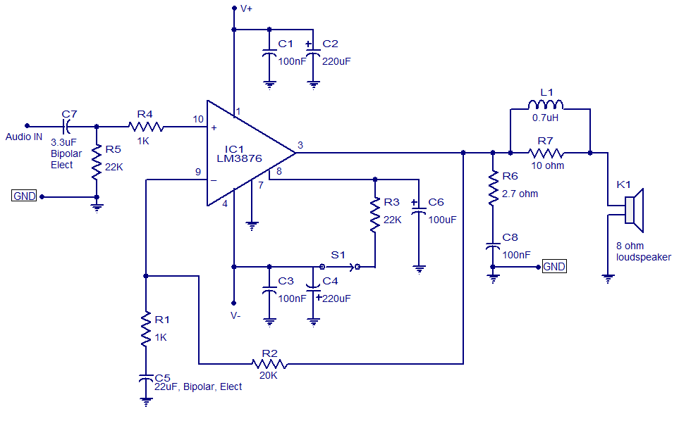
LM3876-based 50-watt audio amplifier circuit. Operates from +/-35V DC. Simple design, low noise. The LM3876 is a high-performance audio power amplifier designed for driving speakers in various audio applications. This particular circuit configuration enables the amplifier to deliver up to...

A simple FM transmitter circuit can be designed using the MC2833 integrated circuit, which is intended for cordless telephone and FM communication applications. This circuit includes a microphone amplifier, a voltage-controlled oscillator, and two auxiliary transistors. The final output...
While I would have liked a 4 channel chip with about 20 Watt per channel, the local parts store didn't have any yet, so I opted for two TA8215AH stereo chips, selected by their low price in this particular...

This compact FM transmitter has a range of approximately 50 meters and is designed for hobbyists. With multiple mini-transmitters, users can create a diverse and engaging radio program. The device achieves high frequency stability due to its power supply...
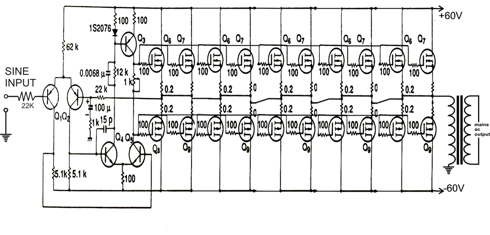
The configuration depicted in the first diagram is a straightforward MOSFET-based design intended for current amplification at +/-60 volts, enabling the connected transformer to produce the required 1 kVA output. Transistors Q1 and Q2 constitute the initial differential amplifier...
Warning: include(partials/cookie-banner.php): Failed to open stream: Permission denied in /var/www/html/nextgr/view-circuit.php on line 713
Warning: include(): Failed opening 'partials/cookie-banner.php' for inclusion (include_path='.:/usr/share/php') in /var/www/html/nextgr/view-circuit.php on line 713