
mp3 fm transmitter

The car MP3 FM transmitter circuit typically consists of several key components that work together to facilitate the transmission of audio signals. At its core, the circuit includes an audio input stage, where the MP3 player or other audio source connects. This input stage is often coupled with a preamplifier, which boosts the audio signal to a suitable level for transmission.
The preamplifier is crucial for enhancing the audio quality, as it minimizes noise and distortion, allowing for a clearer sound. Following the preamplifier, the circuit usually features a modulator stage, which converts the audio signal into an FM signal. This is typically achieved using a voltage-controlled oscillator (VCO) that generates a carrier frequency, which is modulated by the audio signal.
To ensure optimal performance, the circuit may also include a low-pass filter to eliminate any unwanted high-frequency noise that could interfere with the audio quality. Additionally, an antenna is integrated to radiate the FM signal, allowing it to be picked up by nearby FM receivers, such as car radios.
Power supply considerations are also important for the functionality of the circuit. It is common for the circuit to be powered by the vehicle's battery, and voltage regulation components may be included to ensure stable operation.
Overall, the car MP3 FM transmitter circuit is a versatile and effective solution for broadcasting audio from portable devices to FM receivers, providing users with the convenience of wireless audio playback in their vehicles.Car Mp3 FM transmitter circuit. This circuit can broadcast any audio to FM receiver. It has a good preamplifier circuit so the broadcast sound quality is good.. 🔗 External reference
Related Circuits
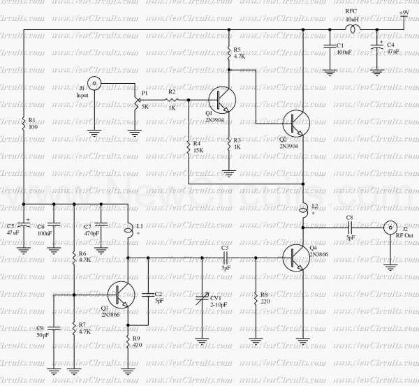
In this project, you will make a simple 3-stage low-power broadcast-type circuit, using a crystal oscillator integrated circuit and a collector modulated AM oscillator with amplifier. You can connect the circuit to an electret microphone or amplified dynamic microphone....
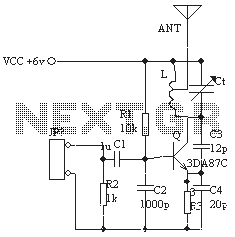
The ordinary triode 3DA87C is utilized to create a long-range FM transmitter circuit, which functions as a standard three-point oscillator circuit. This remote transmitter circuit is capable of large current emissions, achieving a range of up to 1 kilometer...
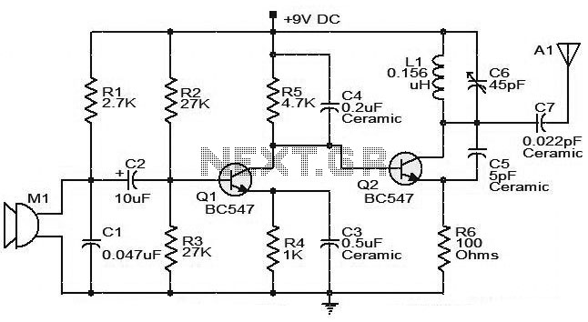
The moderate power FM transmitter circuit employs two transistors. The voice signals picked up by the microphone will be amplified by the transistor. The described FM transmitter circuit utilizes two transistors to facilitate the modulation and amplification of audio signals....
The most important part of this 88-108 transmitter is the Colpitts oscillator. Capacitors C3, C4, C5, C6, diodes CD1 and CD2, and inductor L1 determine the transmission frequency. The RF oscillator... The Colpitts oscillator is a type of electronic oscillator...
This circuit is a powerful video sender in VHF band. The modulator section is designed to operate on either channels 7 to 13 or 14 to 29. For channels 7 to 13, L1 and L2 are 3 turns of...
In many discussions of LPAM transmitter design, references to "the Wenzel circuit" or "the Wenzel transmitter" are common. These terms refer to a clever transmitter design that became popular in the mid-1990s and early 2000s for those interested in...