
3 6 volt cell phone battery meter

The circuit operates by monitoring the voltage of the lithium-ion battery and translating this voltage into a visual representation through the LED bar graph. The TL431 acts as a precision voltage reference and is adjustable, allowing for fine-tuning of the voltage level that corresponds to the activation of the LEDs.
The four LEDs are arranged in a bar graph format, where each LED illuminates based on the battery voltage level. As the battery voltage increases, more LEDs will light up, providing a clear visual indication of the battery's state of charge. The use of the 1K resistor in conjunction with the TL431 ensures that the reference voltage is stable and can accurately control the activation of the LEDs.
The 5K adjustable resistor allows for calibration of the lower threshold, ensuring that the first LED lights up at the desired voltage level, which is critical for accurate battery monitoring. This feature is particularly useful for applications where the battery voltage needs to be closely monitored to prevent over-discharge, which can damage lithium-ion cells.
Overall, this circuit provides an effective and efficient means of displaying battery voltage levels, making it a valuable addition to battery-powered devices where visual feedback on battery status is essential.This is a similar circuit to the above and provides a 4 LED bar graph indicating the voltage of a common 3.6 volt Lithium - Ion recharable cell phone battery. The reference voltage is provided by a TL431 programmable voltage source which is set to 3.9 volts where the TL431 connects to the 1K resistor.
The lower reference for the LED at pin 14 is set with the 5K adjustable resistor.. 🔗 External reference
Related Circuits
A 10 bit scanning voltmeter with a Minimum Mass Wireless Coupler, based on the ATMega8. Range to the Minimum Mass Base Unit is 10 to 15 cm. If the voltmeter is battery operated, it can be floated from ground....
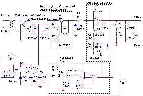
The switching power supply, shown in the schematic, provides 12 volts, at 10 amps, maximum, using a discrete transistor regulator with an op-amp functioning as a comparator in the feedback circuit. The supply was constructed in 1984 and is...
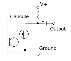
A simple circuit is desired that utilizes a microphone to capture voice and transmit the audio signal to a speaker. The objective is to understand the connections required for integrating a microphone into the circuit. To create a basic microphone-to-speaker...
The circuit is designed to be installed in a small enclosure, which can be positioned according to preference. It requires only three connections: one for the positive terminal of the battery, one for the +5 volts supplied by the...
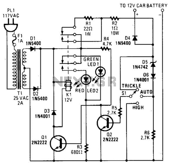
The circuit is capable of supplying either a trickle charge (50 mA) or a high-current charge (1 A). Users can select either charging method or an automatic mode that initially trickle charges a battery if it is particularly low...
The PTB78560x is a series of 30 W rated isolated DC/DC converters designed to operate from a standard 24 V or 48 V telecom central office (CO) supply. Housed in a 12 package, each model features a wide adjustable...