
3.6 Volt cell phone battery meter circuit

The circuit employs a TL431 voltage reference to create a stable reference point for the LED indicators. The TL431 is a programmable shunt voltage reference that can be adjusted to provide a desired output voltage, in this case, set to 3.9 volts. This voltage level is crucial for accurately representing the battery voltage on the LED bar graph.
The 1K resistor connected to the TL431 serves to limit the current flowing through the reference pin and helps in establishing the desired output voltage. The 5K adjustable resistor allows for fine-tuning of the lower threshold voltage at pin 14, which controls the activation of the LED indicators. By adjusting this resistor, the user can set the point at which the first LED lights up, indicating that the battery voltage has reached a specific lower limit.
The 4 LED bar graph visually represents the battery voltage level, with each LED corresponding to a specific voltage range. When the battery voltage is above the set threshold, the corresponding LEDs will illuminate, providing an immediate visual indication of the battery status. This circuit is particularly useful in portable electronic devices, where monitoring battery levels is essential for ensuring optimal performance and preventing unexpected shutdowns.
Overall, the design is straightforward yet effective, utilizing common electronic components to achieve a functional and user-friendly battery voltage monitoring solution.This is a similar circuit to the above and provides a 4 LED bar graph indicating the voltage of a common 3.6 volt Lithium - Ion recharable cell phone battery. The reference voltage is provided by a TL431 programmable voltage source which is set to 3.9 volts where the TL431 connects to the 1K resistor.
The lower reference for the LED at pin 14 is set with the 5K adjustable resistor.. 🔗 External reference
Related Circuits
With a 1.5V battery supply, the integrated circuit LM3909 can drive the light-emitting diode NSL5027. The 300μF electrolytic capacitor acts as a timing capacitor, which limits the flash speed to approximately 1Hz. The circuit utilizes the LM3909, a popular LED...
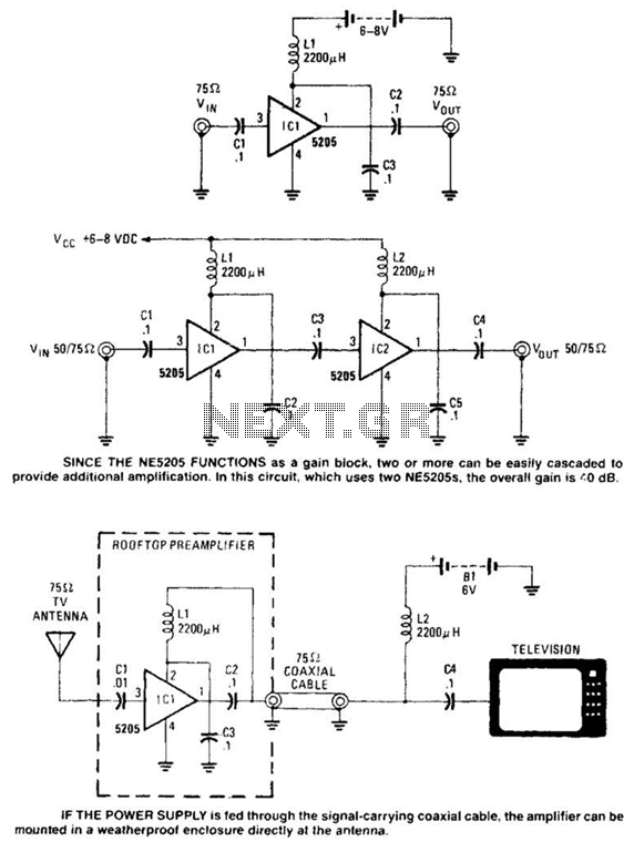
Except for the coupling and decoupling capacitors, IC1 is a complete wideband amplifier that has a fixed gain of 20 dB up to 450 MHz. No external compensation is required. Since the NE5205 functions as a gain block, two...
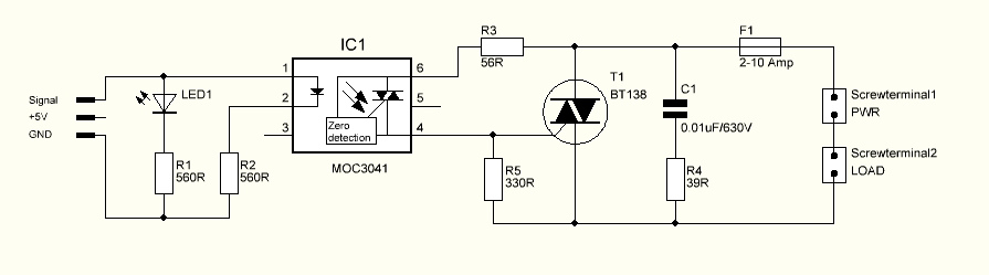
The triac is expected to activate and illuminate the light at nearly 100% brightness; however, it does not turn on at all. If the gate is continuously triggered (i.e., a constant voltage is applied to the gate), the light...
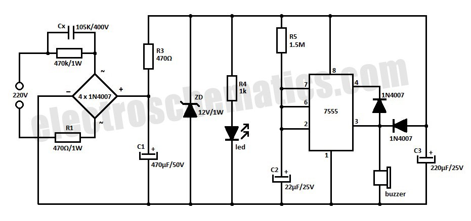
This is a simple power resumption alarm circuit that can be installed within the switch box. It emits beeping sounds when power is restored following a power failure. The power resumption alarm circuit is designed to provide an audible alert...
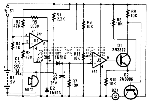
In the circuit, U1 amplifies the audio captured by the condenser microphone. Resistor R1 limits the current, while R2 and R3 center the amplifier's output to a voltage level of %B+ to facilitate the use of a single-ended power...
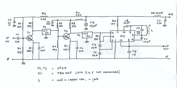
Two conventional amplifier stages built with SF215 transistors are linked by ceramic 10.7MHz IF filters, and followed by an FM demodulator built with a TBA120T i.c. Straight from the databook. Output goes via a 100k log potmeter (not shown)...