
Crystal symbols and equivalent RLC circuit

The crystal equivalent RLC circuit is a fundamental electronic circuit that models the behavior of a crystal oscillator. This circuit comprises a resistor (R), inductor (L), and capacitor (C), which can be arranged in either a series or parallel configuration.
In a series resonant circuit, the inductor and capacitor are connected in series with the resistor, and the total impedance is minimized at the resonant frequency, allowing maximum current to flow. This configuration is particularly useful for applications requiring high selectivity, such as in radio frequency (RF) applications.
Conversely, in a parallel resonant circuit, the inductor and capacitor are connected in parallel with the resistor. At the resonant frequency, the impedance is maximized, which allows the circuit to effectively filter signals. This configuration is often employed in applications where high voltage gain is needed, such as in oscillators and filters.
The resonant frequency (f₀) of the RLC circuit can be calculated using the formula:
f₀ = 1 / (2π√(LC))
where L is the inductance in henries and C is the capacitance in farads. The quality factor (Q) of the circuit, which indicates the sharpness of the resonance peak, can be defined as:
Q = (f₀ / Δf)
where Δf is the bandwidth of the circuit. A higher Q factor indicates a narrower bandwidth and better selectivity.
In practical applications, the choice between series and parallel configurations depends on the specific requirements of the circuit, including the desired frequency response, impedance matching, and power handling capabilities. Proper selection and tuning of the R, L, and C components are crucial for achieving optimal performance in crystal oscillator applications.Crystal equivalent RLC circuit is shown. RLC circuit is a series-parallel, you can use a series resonant or parallel resonant manner style to operate.
Related Circuits
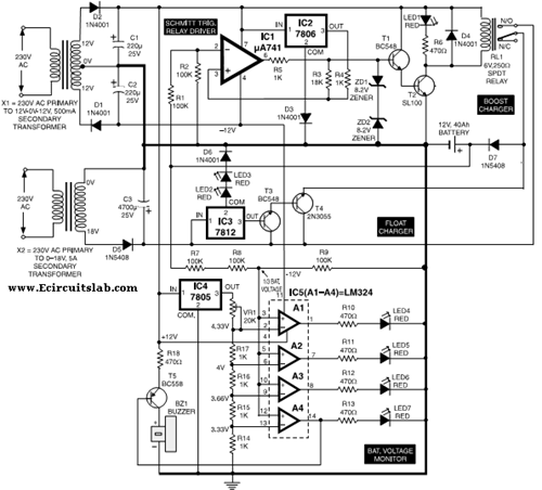
This circuit illustrates the use of the 7806 IC in an automatic battery charger circuit diagram. It is designed for a car battery with an approximate rating of 40 Ah. The automatic battery charger circuit utilizing the 7806 integrated circuit...
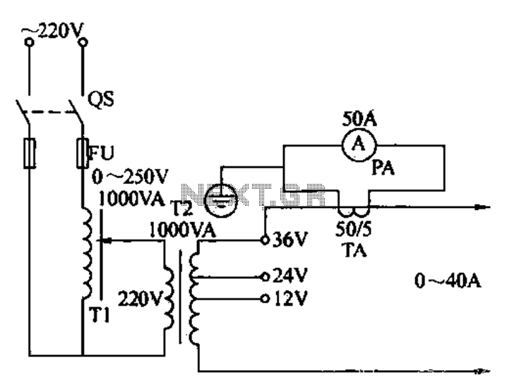
Electricians sometimes use overcurrent relays, thermal relays, and other devices to perform periodic overcurrent checks with a current generator. A secure running lights transformer, voltage regulator, and meter can be constructed using a small electric current generator. The homemade...
Long-distance infrared transmitter circuit diagram. This simple circuit offers a considerable range by utilizing three infrared transmitting LEDs (IR1 through IR3) in series to enhance the radiated power. To further improve directivity and power density, the IR LEDs can...
The following circuit illustrates a Bluetooth-based smart home circuit diagram. This circuit is based on the ULN2003 integrated circuit (IC). Features include an LCD and LED. The Bluetooth-based smart home circuit utilizes the ULN2003 IC, which is a high-voltage, high-current...

The purpose of this circuit is to maintain a permanent magnet DC motor at a constant speed, which is set externally. This is achieved by monitoring the current flowing through and the voltage across the motor's brushes. The schematic for...
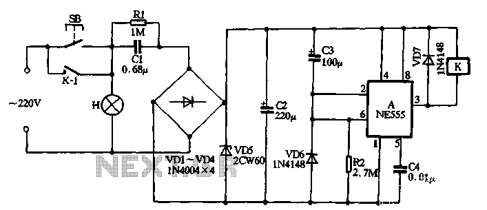
The NE555 push-button delay lamp circuit is illustrated in Figure 3-5. This circuit features several components, including a power supply and relay control system. Typically, the switch SB and normally open relay contacts K1 are in an open state,...