
3 channel audio splitter

The circuit utilizes the NE5532 operational amplifier, known for its low noise characteristics and high fidelity, which is crucial for audio applications. The configuration as a non-inverting amplifier with a gain of 3 means that the output voltage will be three times the input voltage, providing adequate amplification for the audio signal before it is split into three channels. The use of potentiometers R2 and R3 allows for adjustable input levels, enabling fine-tuning of the audio signal before amplification.
Capacitor C2 plays a critical role in blocking any DC offset present in the audio signal, ensuring that only the AC components are amplified and sent to the output channels. The output is then divided among three separate paths through resistors R8, R9, and R10, which can be used to drive different audio devices or channels, maintaining signal integrity across all outputs.
The voltage regulation section of the circuit is essential for providing stable power to the NE5532, ensuring optimal performance. The positive voltage regulator formed by Q1, C3, R6, and D1 supplies the necessary positive voltage, while the negative voltage regulator created by Q2, C4, R7, and D2 provides the negative voltage required for the dual-supply operation of the op-amp. This dual supply configuration enhances the dynamic range and overall audio quality of the circuit.
For applications where a dual power supply is not available, the voltage regulator sections can be utilized to generate the required voltages from a single supply, ensuring versatility in various setups. This circuit design is suitable for a range of audio applications, including mixing consoles, audio interfaces, and other professional audio equipment where high-quality sound reproduction is essential.Here is the circuit diagram of a simple 3 channel audio splitter based on the IC NE5532. NE5532 is a dual internally compensated low noise opamp from Fairchild semiconductors. It has a high small signal and power bandwidth, making it well suitable for high quality audio applications. Here the IC1 is wired as a non inverting amplifier with a gain 3 . The audio signal to be splited is applied to the non inverting pin of IC1 through the POTs R2 and R3. Capacitor C2 works as a DC decoupler and resistors R8, R9, R10 splits the output of the IC1 into three channels.
Components Q1, C3, R6, D1 forms a positive voltage regulator while components Q2, C4, R7, D2 forms a negative voltage regulator. If you have a +12/-12 V dual power supply, then the circuit can be directly powered from it and the regulator sections can be avoided.
🔗 External reference
Related Circuits
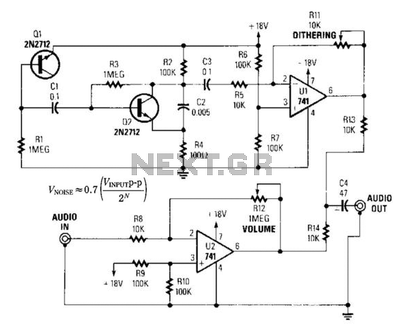
By introducing a small amount of noise to a signal intended for digitization (approximately 0.7 bits), where n represents the number of bits, for instance, an 8-bit signal with a peak-to-peak voltage of 2 V would result in a...
A window comparator formed by two operational amplifiers packaged into IC1 is the heart of the circuit below. With this technique, we can detect precisely and symmetrically. The window comparator circuit utilizes two operational amplifiers (op-amps) configured to create a...
Audio Light Modulator. Audio light modulation enhances the enjoyment of music during events held at home or outdoors. Presented here is a straightforward circuit for this purpose. The audio light modulator circuit is designed to synchronize light effects with audio...
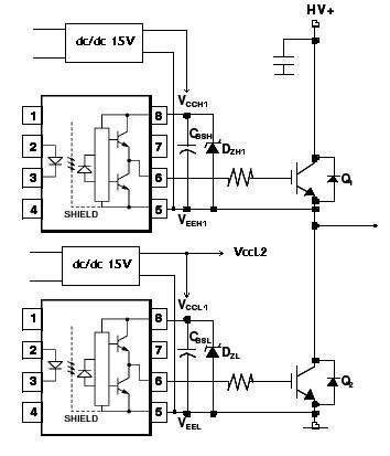
An H-bridge circuit has been developed utilizing four floating gate drivers and four insulated gate bipolar transistors (IGBTs). The attached schematic illustrates one half of the H-bridge configuration. The circuit operates effectively, but there are additional considerations to address. The...
This audio peak detector enables monitoring of a pair of stereo channels using a single LED indicator. The circuit employs identical configurations for both left and right channels. It utilizes the switching levels of Schmitt trigger NAND gates within...

This car audio amplifier circuit is based on the LA47536 audio amplifier integrated circuit designed by Sanyo. This audio amplifier circuit is specifically designed for car audio power amplifiers. The LA47536 car audio amplifier IC features four output channels...