
300A-18V three-phase thyristor power regulator circuit for electrolysis

The 300A-18V three-phase thyristor power regulator circuit is a sophisticated electronic system tailored for high-current electrolysis processes. The design emphasizes efficiency and stability, utilizing thyristors to control the output voltage and current levels. The circuit architecture consists of several critical components: the main power circuit handles the high current, while the trigger circuit activates the thyristors at precise intervals to regulate the power delivered to the load.
The voltage negative feedback system is a crucial feature that enhances stability and performance. By sampling the output voltage from the rectifier, the feedback loop adjusts the operation of the thyristors to maintain the desired output voltage despite variations in load conditions. The use of a reactor L introduces a controlled inductance into the circuit, which helps smooth out fluctuations and provides a stable operating environment. The potentiometer RP allows for fine-tuning of the voltage output, enabling operators to adjust the system to meet specific processing requirements.
Components R23 and C9 form a differential feedback network that further stabilizes the output by responding to changes in load and voltage. This automatic voltage regulation ensures that the system can adapt to varying operational demands without manual intervention, significantly improving reliability.
The integration of a single-junction transistor relaxation oscillator is an innovative approach to generating the necessary trigger pulses for the thyristors. The narrow pulse width produced by this oscillator is essential for the accurate timing of the thyristor firing, which is critical for maintaining the desired output characteristics. The design also incorporates a transformer Ti that is responsible for distributing power across the three phases, effectively balancing the load and enhancing overall system performance.
Finally, the inclusion of a 150W lamp load serves as a practical demonstration of the circuit's capabilities, allowing for real-time testing and validation of the system's performance under operational conditions. This comprehensive design ensures that the 300A-18V thyristor power regulator circuit is not only effective for electrolysis applications but also adaptable for various industrial power supply needs.300A-18V three-phase thyristor power regulator circuit electrolysis It can output DC 3000A, 18V (adjustable), power supply solution processing. Circuit from the main circuit, trigger circuit, part of the synchronous power, DC power, voltage negative feedback
circuit and protection circuit. Voltage negative feedback voltage is removed from the cell (ie, the rectifier output), the reactor L superimposed on a given voltage (by the potentiometer RP to the drawing). Voltage differential negative feedback by the R23 and C9. It plays the role of regulator with automatic voltage negative feedback. Since the single-junction transistor relaxation oscillator output pulse is narrow, in order to make reliable short pulse to trigger the transformer Ti of three phases in parallel a 150W lamp load.
Related Circuits
The circuit comprises a 3-stage resistor-capacitor coupled amplifier. When ring button S2 is pressed, the amplifier circuit formed around transistors T1 and T2 gets converted into an asymmetrical astable multivibrator generating ring signals. These ring signals are amplified by...

This is a versatile digital counter circuit that is cost-effective due to the basic components available in many electronic shops. The digital counter circuit is designed to count pulses and display the count on a digital readout, typically using a...
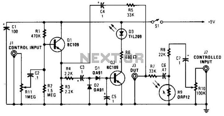
In this circuit, audio input to the control channel is amplified and rectified by diodes D1 and D2. This direct current level activates LED D3 through transistor Q2. The illumination from LED D3 causes R9, a light-dependent resistor, to...
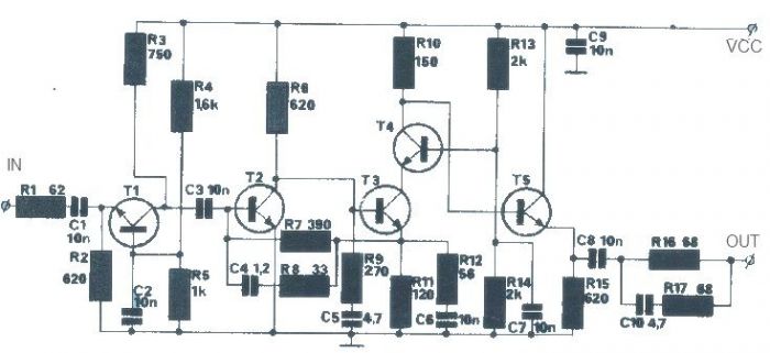
The T1 transistor must be of the BF200 type (or a similar variant), while the other transistors can be of the BF214 type. To achieve high efficiency, the antenna amplifier should be positioned at a short distance from the...
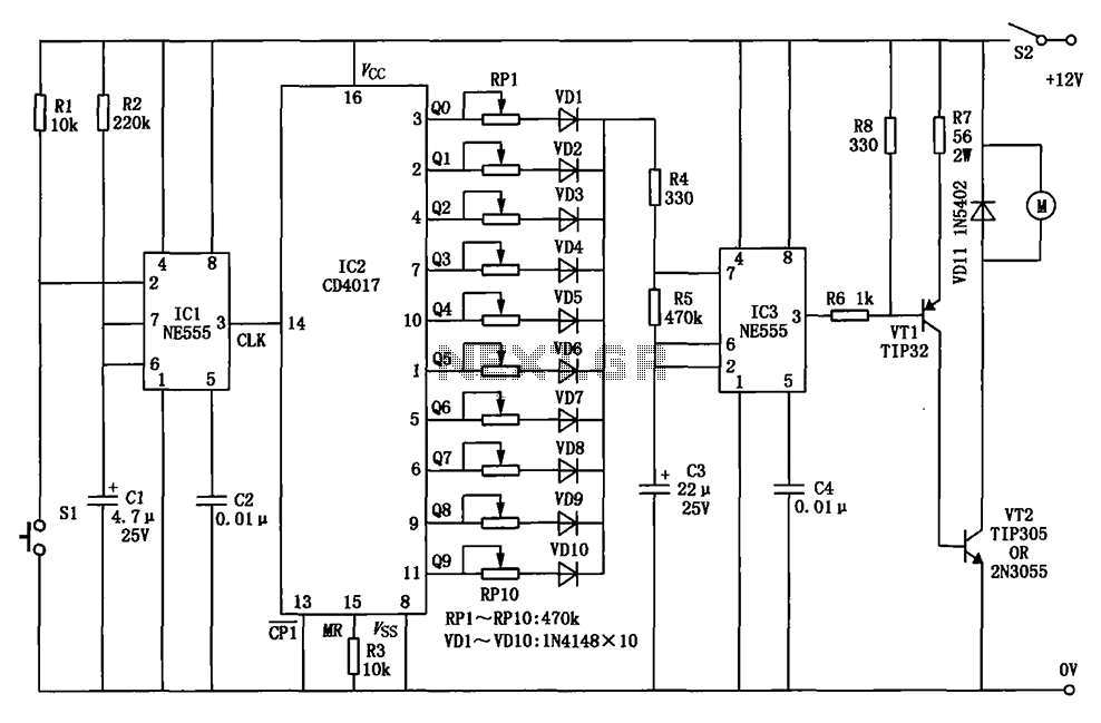
The circuit for a car wiper speed controller allows for adjustable wiper speed, ranging from one to ten cycles per second. This feature enables flexibility in operation and contributes to energy efficiency. The car wiper speed controller circuit typically employs...
33 kW and above windlass with Y-conversion power-saving circuit The circuit design for a windlass rated at 33 kW and above incorporates a Y-conversion power-saving mechanism. This design is crucial for optimizing the efficiency of the windlass, which is commonly...