
300B tube single-ended Class A amplifier circuit diagram

The 300B tube single-ended Class A amplifier is a high-fidelity audio amplification circuit that utilizes a 300B vacuum tube as the primary amplification element. This design is characterized by its simplicity and the warm, rich sound quality it produces, which is highly sought after in audiophile circles.
The circuit typically consists of a power supply, an input stage, a driver stage, and the output stage, which employs the 300B tube. The power supply is designed to provide the necessary high voltage, usually around 300V, and a filament voltage of approximately 5V to power the 300B tube.
In the input stage, a low-noise tube, such as the 6SN7 or 12AX7, is often used to amplify the audio signal before it reaches the driver stage. The driver stage may include another tube that prepares the signal for the output stage, ensuring that the 300B tube operates within its optimal parameters.
The output stage features the 300B tube in a single-ended configuration, meaning that it amplifies the audio signal using only one tube per channel. This configuration results in lower distortion and a more natural sound reproduction. The output transformer is crucial in this stage, as it matches the high impedance of the tube to the lower impedance of the speakers, allowing for efficient power transfer.
Additional components, such as coupling capacitors, resistors, and feedback networks, are included to ensure stability and to tailor the frequency response of the amplifier. The overall design emphasizes minimalism and high-quality components to maintain signal integrity and enhance audio performance.
The 300B tube single-ended Class A amplifier circuit is revered for its ability to deliver a warm and dynamic sound, making it a popular choice for high-end audio systems.300B tube single-ended Class A amplifier circuit is as follows:
Related Circuits
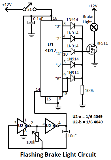
This flashing brake light circuit is designed for motorcycles. When the brake light switch S1 is closed, power is supplied to U1 and U2. The circuit utilizes two inverters from U2. The flashing brake light circuit operates by utilizing a...
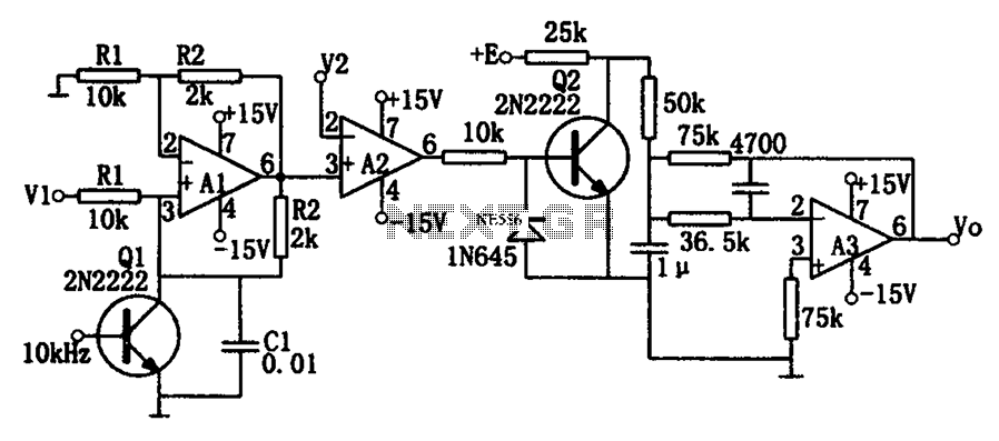
As illustrated in the dividing circuit diagram, A1 consists of a voltage-controlled current source, A2 functions as a voltage comparator, and A3 is configured as an active low-pass filter. When the time constant R1C1 is equal to the clock...
The amplifier is capable of delivering around 1.5W into 8 ohm headphones, and 2.2W into 32 ohms - this is vastly more than will ever be needed in practice. The use of a 120 Ohm output resistor is recommended,...
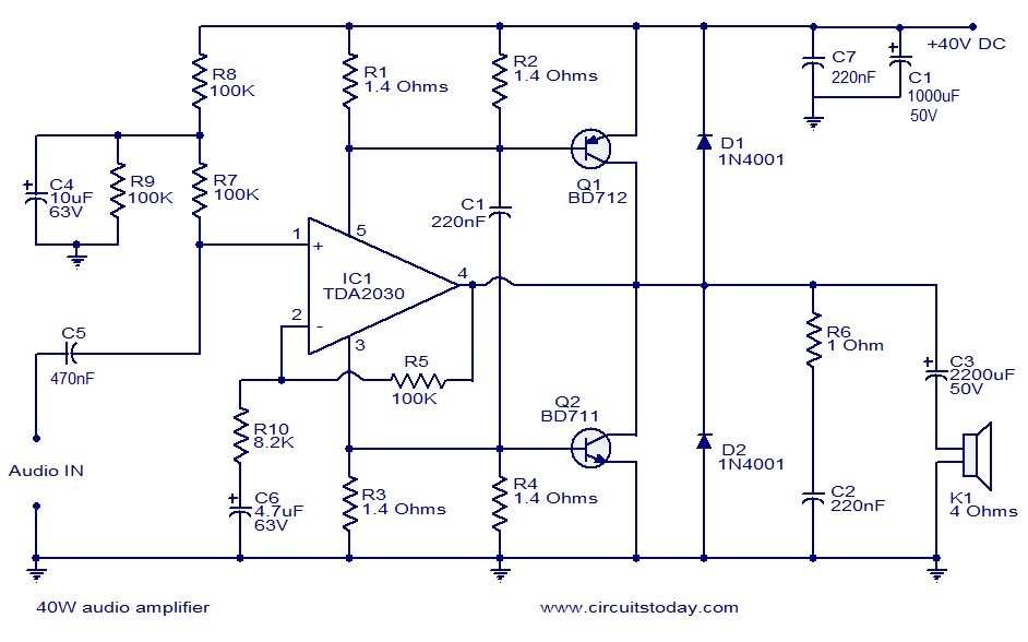
This is a highly effective 40W power amplifier design utilizing the TDA2030 integrated circuit and two transistors. The circuit consists of only a few components and does not necessitate a dual power supply. The input signal is connected to...
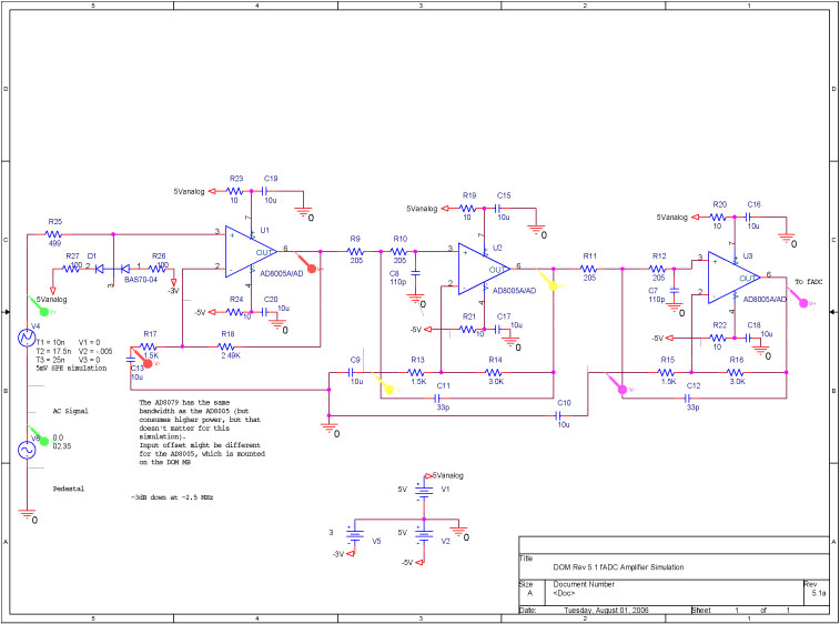
A bandwidth-limited amplifier shapes the waveform sampled by the 40 MHz high-speed pipeline Analog to Digital Converter (fast ADC, or fADC). It is well known that the shaping time is twice the time constant (peaking time) for each pole...
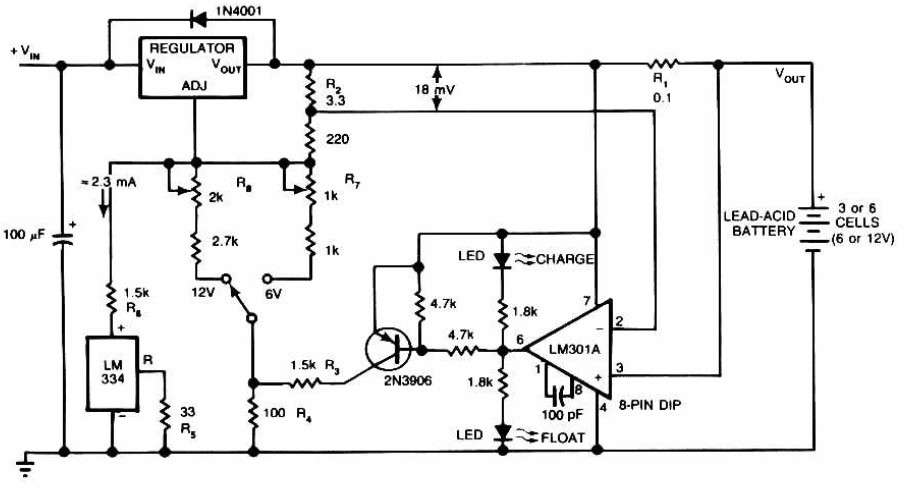
Lead-Acid Battery Charger circuit diagram. The LM301A compares the voltage drop across R1 with an 18 mV reference set by R2. The comparator's output controls the voltage regulator, forcing it to produce the lower float voltage when the battery-charging...