
300m FM Transmitter

This FM transmitter circuit utilizes a few basic components to generate frequency-modulated signals suitable for short-range transmission. The primary components typically include a transistor, a variable capacitor, an inductor, and a power source, which together form an oscillator circuit. The oscillator generates a carrier wave at a specific frequency, modulated by the audio input signal, which can be derived from various sources such as a microphone or audio player.
The circuit operates by allowing the audio signal to vary the frequency of the carrier wave, which is then transmitted through an antenna. The antenna, often a simple wire, radiates the modulated signal into the surrounding area, where it can be picked up by standard FM receivers within the transmission range.
To enhance the performance of the transmitter, careful consideration should be given to the placement and tuning of the inductor and capacitor, as these components determine the operating frequency of the transmitter. Additionally, the power supply should be stable to ensure consistent operation.
A typical application for such a circuit includes personal broadcasting, where users can transmit audio content to nearby FM radios. It is crucial to note that legal restrictions may apply to the use of FM transmitters, and compliance with local regulations regarding transmission power and frequency usage is essential. The simplicity of the circuit makes it an excellent project for educational purposes, allowing individuals to gain hands-on experience in RF transmission and modulation techniques.This FM transmitter circuit is very simple and it has a acceptable transmission . The signal transited from this FM transmitter circuit can be received at.. 🔗 External reference
Related Circuits
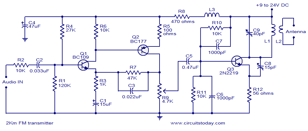
With a matching antenna, the FM transmitter circuit can transmit signals over a range of 2 kilometers. The transistors Q1 and Q2 form a highly sensitive preamplifier stage. The audio signal to be transmitted is coupled to the base...
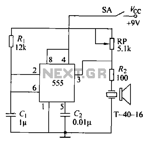
The circuit comprises an ultrasonic transmitter and a T-4 0-16 555 timer circuit. By adjusting the potentiometer RP, the frequency of the oscillation circuit can be modified. The circuit emits ultrasonic signals at a frequency of 40 kHz, with...
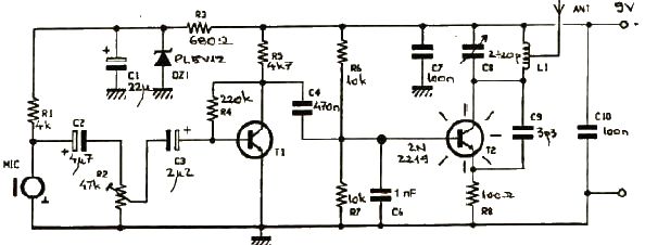
This FM transmitter electronic project operates in the FM band with a transmission power of approximately 250 mW. The circuit is straightforward and utilizes common transistors and electronic components. The T1 transistor, which may be a BC107, BC171, or...
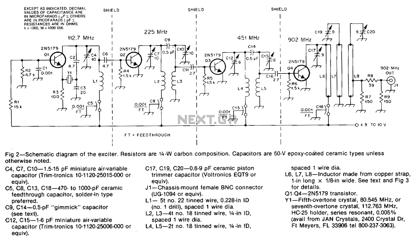
The oscillator, Q1, is a standard overtone circuit. A fifth-overtone crystal, 80.545 MHz, is operated on the seventh overtone, 112.763 MHz. C6 couples the output of the oscillator to Q2, which operates as a doubler to 225.5 MHz. A...
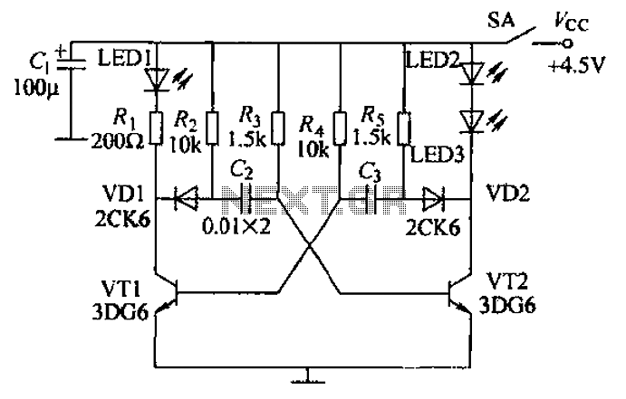
Transistors VT1, VT2, and associated RC components are configured to form a multivibrator. The multivibrator operates with resistors Ra and R4 serving as base bias resistors for VT2 and VT1, respectively. When the switch SA is closed after applying...
You'll find that this is a very easy project to build. It will transmit good quality sound in the FM band (88 - 108 MHz). One important item is that the IC chip operates on 3 volts DC. The...