
300w Mosfet Linear Amplifier For 50 Mhz

The described converter circuit employs a PKS606YN from the PeakSwitch family, which is designed for efficient power conversion applications. This specific device integrates a high-voltage power MOSFET, a PWM controller, and necessary protection features, making it suitable for driving loads such as motors. The motor in question has a nominal rating of 36 W, but the design accommodates peak demands of up to 72 W, ensuring reliability during startup and transient conditions.
Two methods are implemented for speed control of the motor. The first method involves a potentiometer (R20) connected to terminal J3, allowing for manual adjustment of the motor speed. This method provides a simple user interface where the resistance can be varied to change the output voltage, thus controlling the motor speed.
The second method for speed control utilizes an external voltage source connected to terminal J4. This voltage source can vary between 3.6 V and 10 VDC, providing flexibility in how the motor speed is adjusted. By applying a specific voltage within this range, the output voltage of the power supply is modulated, directly influencing the motor's operational speed.
Overall, the circuit design emphasizes versatility and user control over the motor's speed while ensuring robust performance under varying load conditions. The integration of the PeakSwitch component enhances efficiency and simplifies the overall design, making it suitable for various applications requiring precise motor control.The converter shown in Figure 1 uses a member of the PeakSwitch family (U1, a PKS606YN) to drive a 36 W motor, while delivering startup and load transition peaks of up to 72 W. The motor`s speed is variable by two methods: 1) potentiometer R20 (connected to J3), or 2) an externally supplied 3.
6 V to 10 VDC voltage source (connected to J4 ). The motor speed controls vary the output voltage of the supply. 🔗 External reference
Related Circuits
Schematic diagram and description of a 2-watt audio amplifier circuit using the TDA7052 amplifier IC. This is a very simple audio amplifier circuit. The 2-watt audio amplifier circuit utilizing the TDA7052 integrated circuit (IC) is designed for basic audio amplification...
The XLR connector facilitates the connection of the microphone's output to the preamplifier circuit. This preamplifier was designed and constructed by Electrical Engineers using discrete components. The signal from the preamplifier is subsequently fed to the Maxim Class-D amplifier....
The objective of this design was to create a combo amplifier reminiscent of those commonly found in the 1960s and 1970s. This amplifier is particularly suitable for guitar applications but can also effectively amplify any electronic musical instrument or...
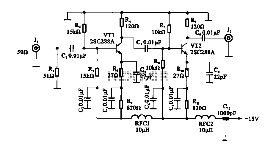
The circuit consists of a two-stage common emitter amplifier, which serves as a practical wideband amplifier. It utilizes capacitors for coupling between the input and output stages. The emitter decoupling capacitor, C4, is employed to eliminate AC negative feedback,...
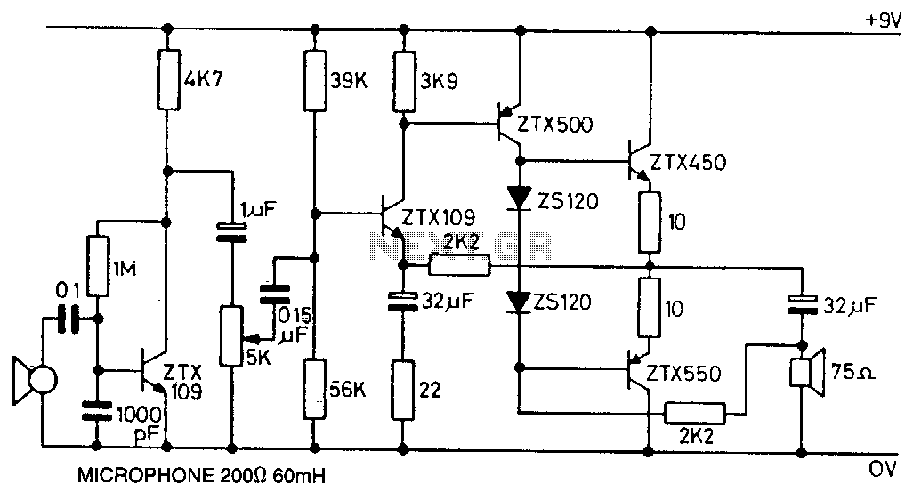
This circuit utilizes the ZTX450 and ZTX550 transistors configured in a push-pull output stage. The following measurements were recorded at maximum volume: Input: 0.4 mV rms, Output: 1.8 V rms, Voltage gain: 4500, Maximum output before distortion: 2.25 V...
This delay can be used in power amplifiers to prevent the fuses from failing when the amplifier is turned on. The circuit is very simple with a relay that is turned on when C2 and C3 are charged. If...