
Guitar Amplifier

The combo amplifier circuit integrates a two-stage design that enhances audio fidelity and versatility. The two-FET preamplifier stage is responsible for amplifying the input signal while maintaining low noise levels, which is essential for high-quality sound reproduction. The choice of FETs allows for high input impedance, making the amplifier suitable for a variety of input sources, including passive guitar pickups and microphones.
The amplifier features dual inputs, each designed for different sensitivity levels. This allows performers to connect various instruments without the need for additional gain stages or external preamps, facilitating a user-friendly experience. The treble-cut control provides tonal shaping, enabling users to tailor their sound to suit different musical styles and preferences.
The output stage employs a Darlington transistor configuration, known for its ability to deliver high current gain and efficiency. The integration of the sensing transistor (Q4) in close proximity to the output transistors ensures accurate temperature monitoring, which is critical for maintaining the reliability and longevity of the amplifier. By utilizing a TO126-case transistor, the design simplifies the thermal management process, allowing for effective heat dissipation.
Overall, this combo amplifier design not only pays homage to the classic models of the past but also incorporates modern advancements to enhance performance and usability, making it a versatile choice for musicians and audio enthusiasts alike.The aim of this design was to reproduce a Combo amplifier of the type very common in the `sixties and the `seventies of the past century. It is well suited as a guitar amplifier but it will do a good job with any kind of electronic musical instrument or microphone.
5W power output was a common feature of these widespread devices due to the general adoption of a class A single-tube output stage (see the Vox AC-4 model). Furthermore, nowadays we can do without the old-fashioned Vib-Trem feature frequently included in those designs. The present circuit can deliver 10W of output power when driving an 8 Ohm load, or about 18W @ 4 Ohm.
It also features a two-FET preamplifier, two inputs with different sensitivity, a treble-cut control and an optional switch allowing overdrive or powerful treble-enhancement. In all cases where Darlington transistors are used as the output devices it is essential that the sensing transistor (Q4) should be in as close thermal contact with the output transistors as possible.
Therefore a TO126-case transistor type was chosen for easy bolting on the heatsink, very close to the output pair. 🔗 External reference
Related Circuits
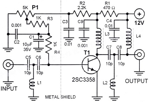
This HD TV UHF wideband amplifier (Ultra High Frequency amplifier) provides a total gain of 10 to 15 dB within the frequency range of 400 to 850 MHz, making it suitable for areas with weak TV signals. To ensure...

This audio amplifier circuit, connected to 32 Ohm impedance mini-earphones, can detect very remote sounds. Useful for theatre, cinema and lecture goers: every word will be clearly heard. You can also listen to your television set at a very...

The TDA 2030 is a widely used 14W audio power amplifier monolithic integrated circuit in a Pentawatt package, intended for use as a low-frequency Class AB amplifier. Some home theater prototypes utilize the TDA 2030 as a low-frequency subwoofer...
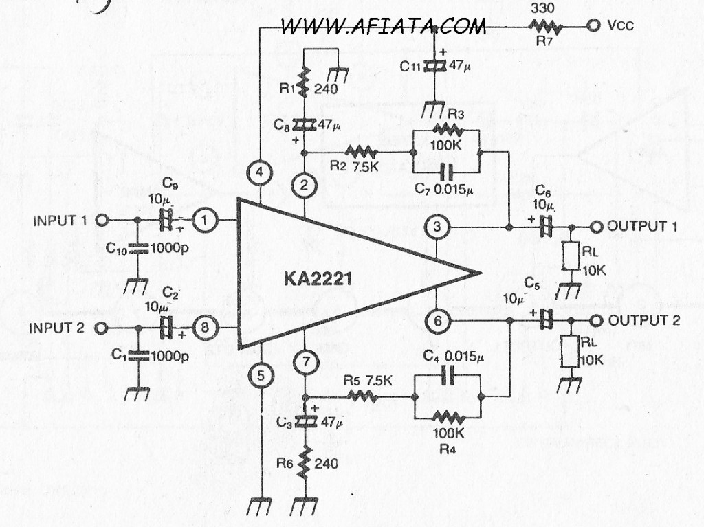
Audio amplifier circuit board with a dual low noise equalizer amplifier. The KA2221 is a monolithic integrated circuit that features 2-channel low noise amplifiers and a regulated power supply designed for car stereos. Key features include suitability for car...
This is a simple microphone preamplifier circuit which you can use between your microphone and stereo amplifier. This circuit amplifier microphone suitable for use with normal home stereo amplifier line/CD/aux/tape inputs. This mic preamp can take both dynamic and...
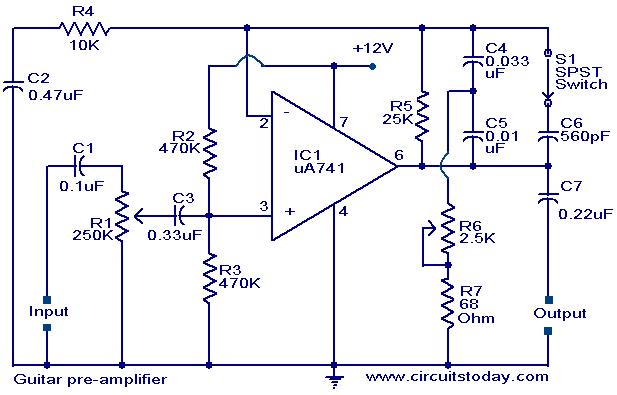
A preamplifier circuit designed for high-impedance electric guitar pickups is presented. This circuit utilizes a uA 741 operational amplifier (IC1) configured as a non-inverting amplifier. The potentiometer R1 functions as a volume control, while potentiometer R6 serves as a...