
3volt fm transmitter for 88mhz
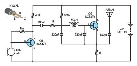
The circuit operates based on the fundamental principles of the Colpitts oscillator, which utilizes an LC tank circuit for frequency generation. The capacitors (C3, C4, C5, C6) and inductance (L1) create a resonant circuit that defines the frequency of oscillation. The BF982 MOSFET, known for its high input impedance, minimizes loading on the tank circuit, thereby maintaining the integrity of the oscillation frequency. The dual gate configuration allows for enhanced control over the oscillator's performance and phase characteristics.
The BF199 transistor amplifies the output signal from the oscillator, ensuring that the signal is strong enough to drive the second stage. The use of a constant load in this stage stabilizes the operating point, which is critical for maintaining linearity and minimizing distortion. The subsequent BFR90 stage further boosts the signal, making it suitable for transmission through the antenna.
In terms of antenna design, the choice of a short copper wire is practical for low-power applications, as it provides sufficient reception and transmission capabilities without the need for a larger structure. The circuit's low output power suggests that it is intended for short-range communication or experimentation, where high gain antennas may not be necessary. Overall, this circuit configuration is efficient for generating and amplifying signals in low-power applications, making it suitable for various electronic projects.The important allotment of the circuit is formed of the Colpitts blazon oscillator. C3, C4, C5, C6, CD1-CD2 and L1 determines the frequency. BF982 and bifold aboideau MOSFET are alive genitalia in oscillator. When the ascribe impedance of the MOSFET aboideau inputs are high, LC catchbasin is not affected. However transistors force the LC catchbasin an d account appearance shift. Two disciplinarian stages are added to abstract the antenna from oscillator. First date (BF199) amplifies the low arresting of the oscillator and works as a connected load. The additional date (BFR90) amplifies the arresting activity through the antenna some more. A abbreviate chestnut wire can be acclimated as an antenna here. Attaching a ample antenna to this ambit is accidental because the achievement ability is low. 🔗 External reference
Related Circuits

This tracking transmitter consists of four distinct subassemblies: a free-running multivibrator, a transmit switch, an audio-tone generator, and an FM transmitter. The multivibrator, which produces a pulse width with a pulse separation of 1500 ms, is built around Q1...
An LMX1601 Phase locked loop, a discreet FET VCO, and an AVR microcontroller combine to make a stable, easy to use monophonic FM transmitter that includes an audio activated switch that turns the transmitter on only when it is...
This transmitter project is a highly efficient, rugged, and simple low-power continuous wave (C.W.) unit delivering more than 10W. It is crystal-controlled with stabilized high tension (H.T.) and features a buffer stage between the crystal oscillator and power amplifier...
This AM transmitter is designed for simplicity and ease of construction. It utilizes a single-winding inductor that is not tapped, eliminating the need for custom winding. A readily available RF choke, such as the Jaycar Cat LF-1536, can be...

This is a simple circuit design for a video transmitter capable of radiating signals up to 50 meters. The video transmitter can be connected to a camera as a source and allows viewing on a VHF channel analog television....
Tetsuo Kogawa's circuit is well documented, although not in a conventional schematic form. It has been entered into LTSpice for analysis, and the schematic is presented online with some comments. The circuit includes a small air variable capacitor (C1)...
Warning: include(partials/cookie-banner.php): Failed to open stream: Permission denied in /var/www/html/nextgr/view-circuit.php on line 713
Warning: include(): Failed opening 'partials/cookie-banner.php' for inclusion (include_path='.:/usr/share/php') in /var/www/html/nextgr/view-circuit.php on line 713