
valved transmitter for 3.5 MHz

The transmitter circuit is designed to deliver reliable and high-quality C.W. signals, suitable for amateur radio applications. The use of valves instead of transistors allows for greater robustness and ease of replacement, making it an appealing choice for hobbyists. The modular design, with separate units for the transmitter and power supply, enhances flexibility and usability, allowing for connection to various equipment. The careful selection of components and circuit design ensures that the transmitter operates efficiently, producing a clean signal that meets the expectations of amateur radio operators. The inclusion of a low-pass filter is a prudent measure to mitigate potential interference and ensure compliance with regulatory standards. Overall, this transmitter project represents a well-thought-out approach to amateur radio transmission, balancing performance, reliability, and ease of use.This transmitter project is a highly efficient, rugged and simple, low power c. w. unit delivering more than 10W. As it`s crystal controlled with stabilised h. t. , and a buffer stage between the crystal oscillator and power amplifier stages, it produces an exceptionally clean c. w. performance. Many amateurs will have some, if not all, of the necessary parts. However, some components are readily available from advertisers of surplus or new components, and other sources such as rallies. The project uses a simple circuit as the transmitter uses valves. All the valves used are readily available, and can be overrun and abused - unlike many transistors! If the valves fail, you just pull them out and plug in a replacement. Remember that valves which were designed before the Second World War are still in use, so they must be considered reliable and worthy of use.
The two separate units are interconnected with a cable and plug socket assembly. This is done so that the power supply unit (p. s. u. ) can be used with other equipment. However, the circuits and layouts I`m describing can be amalgamated into one chassis/cabinet to provide a complete transmitter with integral power unit. The dimensions are not critical. Practically speaking, any suitable chassis/cabinet(s) can be used for the project. No real attempt at miniaturisation was made. The object was reliability, making it easy to build and easy to service. Conventional, well tried and tested circuitry has been used throughout. Signal strength with stability, quality and reliability was my target. The good quality of the resulting c. w. signal has been remarked on by other stations during QSOs. Any a. c. existing p. s. u. providing 250-300V d. c. at 100mA, plus a 150V stabilised supply would be suitable. Two 6. 3V heater windings of at 15 amp minimum are required. The transmitter line up, Fig. 1, consists of a crystal oscillator stage, a buffer amplifier and a p. a. output stage. The suggested power unit, Fig. 2, consists of a valve full wave rectifier and a voltage stabiliser. The crystal oscillator stage uses an EF80/6BX6 valve (V1) in a simple Pierce Colpitts crystal oscillator.
This particular layout using g2 of the valve, V1, as an anode is called an electron coupled oscillator. The oscillator output is buffered by the anode circuit of V 1. The crystal socket (I used FT243 crystals) is mounted on the front panel of the transmitter unit. The oscillator is fed with stabilised hi supply (150V). There is a bit of luxury with a crystal type oscillator, but this technique ensures you ofvery clean and stable signals.
The power amplifier uses a 6BW6 valve (V3) which is rated at 11 to 12W input according to an old ARRL Handbook I have. The 6BW6 is supplied with 280V h. t. positive on the prototype, and uses a well tried and proven circuit. A conventional network output tuned circuit is used to match 750 coaxial feedlines to a suitable antenna via a suitable matching unit.
V1, V2 and V3 use B9A valve bases. Editorial note: We strongly recommend, that to reduce possible EMC problems, that this transmitter be used in conjunction with a low pass filter unit. It should be connected between the output and the antenna tuning unit The filter should have a sharp cut-off above 30MHz.
A 100mA meter is wired into the anode circuit for tuning and loading purposes, and monitoring the anode h. t. current. By measuring the h. t. voltage on the anode circuit, and multiplying it by the anode current reading on the meter, you`ll have the p.
a. power input in watts. The a. c. power unit I used provides 280V h. t. , plus a stabilised voltage of 150 d. c. for the crystal oscillator. It consists of a mains transformer in a full-wave rectifying circuit using an EZ81/6CA4 rectifier valve (B9A base). The 0A2 voltage stabiliser (B7G base) valve is used to provide the 150V h. t. line. A small 6V dial light bulb is wired into the heater circuit, and pa 🔗 External reference
Related Circuits
A low power FM pirate radio. The output power is approximately +35 dBm (3.16 watts) over a 50-ohm load and operates on a +24-volt power supply. The project consists of a Hartley oscillator (modulated VCO) and three stages (Class...
A highly effective 1-watt FM transmitter circuit that is easy to construct. The circuit consists of four transistors: one functions as a stable oscillator, followed by a buffer stage to maintain frequency stability during adjustments. Next is a resonance...

This is a 2 MHz crystal circuit utilizing a CMOS pair. This circuit is suitable for applications in digital watches and clocks due to its low power consumption. The 2 MHz crystal oscillator circuit employs complementary metal-oxide-semiconductor (CMOS) technology, which...
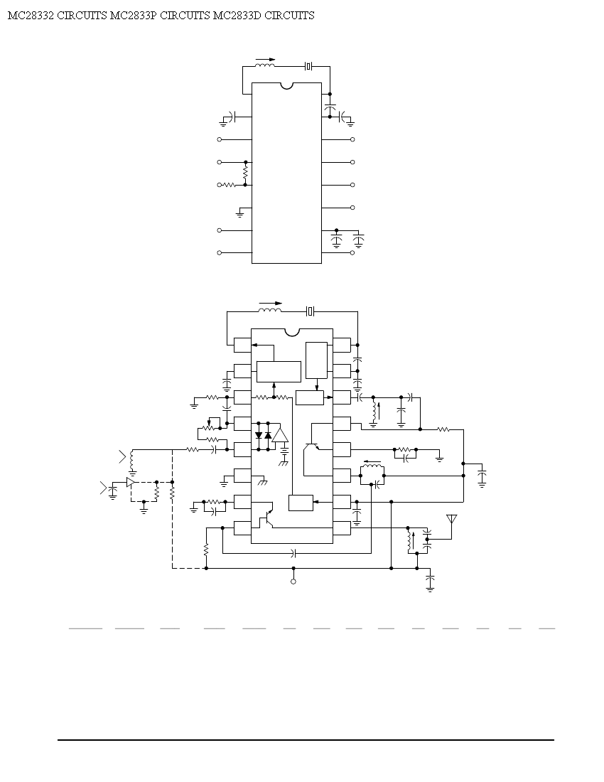
Crystal X1 operates in fundamental mode and is calibrated for parallel resonance with a load capacitance of 32 pF. The final output frequency is produced through frequency multiplication within the MC2833 integrated circuit (IC). The RF output buffer at...
I designed this circuit. It can be connected to an FM tuner to play FM stations on an AM radio. This circuit serves as an interface between an FM tuner and an AM radio, allowing the reception of FM stations...
A copy from an old Italian magazine of amateur electronics proposed an add-on for tube receivers. The add-on was a simple one-tube short-wave transmitter leveraging the same power supply already available in the receiver. The project reported in that...