
455Khz If Amp For 1.5V Operation Circuit

The ZN416E is a versatile integrated circuit designed for use as a 455-kHz intermediate frequency (IF) amplifier. This configuration is particularly useful in various radio communication applications, where amplification of the IF signal is necessary for effective demodulation and further processing. The performance of the amplifier is heavily influenced by the components used in the circuit, particularly the resonator.
In this specific setup, RES1, which is a Murata CSB455E ceramic resonator, plays a critical role in determining the center frequency and bandwidth of the amplifier. The Murata CSB455E is designed to provide high stability and low insertion loss at the 455-kHz frequency, ensuring that the amplifier operates efficiently within its intended parameters. The resonator's characteristics—such as its quality factor (Q) and temperature stability—are essential for maintaining the desired frequency response and minimizing distortion.
The circuit design typically includes additional components such as resistors, capacitors, and possibly additional inductors, which work in conjunction with the ZN416E and RES1 to optimize performance. The selection of these components must be done carefully to achieve the desired gain, noise figure, and linearity of the amplifier. Proper PCB layout practices should also be employed to minimize parasitic effects and ensure reliable operation.
In summary, the ZN416E configured as a 455-kHz IF amplifier, with the Murata CSB455E ceramic resonator, provides a robust solution for intermediate frequency amplification in various RF applications. The careful selection and arrangement of components are crucial to achieving optimal performance. The ZN416E can be configured as a simple 455-kHz IF amplifier. In this case, the circuit`s center and bandwidth are set by RES1 (a Murata CSB455E ceramic resonator).
Related Circuits
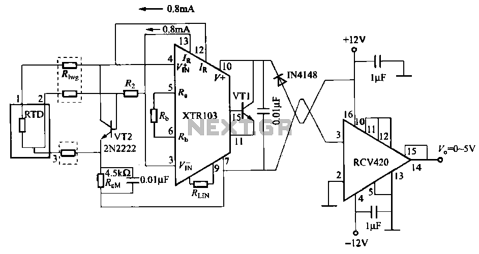
When the RTD temperature sensor is positioned far from the amplifier, the resistance of the sensor leads and their susceptibility to interference and other issues cannot be overlooked. The circuit shown in the figure addresses this problem. It utilizes...
This circuit will impose a maximum slew rate on a signal; positive and negative rates can be independently controlled. The circuit is useful in servo applications where the error signal needs to be limited to be within the power...
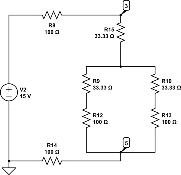
The Delta configuration of resistors R2, R3, and R4 is converted to a Wye (Y) configuration. This conversion is necessary because a voltage divider is typically employed in series circuits. The aim is to determine the total resistance in...
Class D amplifiers are significantly more efficient than traditional amplifiers; however, this high efficiency is accompanied by increased noise and distortion. The frequency and time-domain characteristics of a Class D amplifier, including its output filter, can be evaluated using...
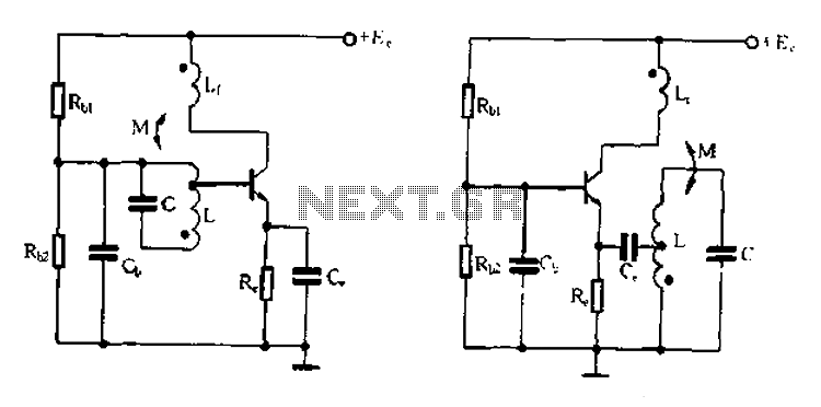
Base frequency selection, frequency-selective emitter type transformer coupled oscillator circuit The described circuit is a transformer-coupled oscillator that utilizes an emitter type configuration to achieve frequency selection. This type of oscillator is designed to generate signals at specific base frequencies,...
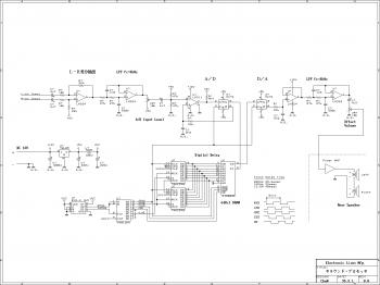
This is an easy-to-build surround sound processor circuit utilizing the digital delay processing method. This audio processor does not employ any specialized function integrated circuits that are difficult to obtain, and it is designed using only common-purpose integrated circuits....