
5 Band Graphic Equalizer Circuit

The graphic equalizer circuit based on the LA3600 IC is designed to enhance audio signals by allowing users to adjust the frequency response across various bands. The LA3600 integrates a gyrator circuit, which emulates an inductor using transistors and capacitors, thus enabling the creation of adjustable band-pass filters without the need for bulky inductive components.
In this configuration, external capacitors are strategically connected to the chip to define the center frequencies and bandwidths of the equalization bands. The circuit typically features multiple frequency bands, allowing for precise control over bass, midrange, and treble frequencies. This adaptability makes it suitable for various applications, including home audio systems and portable devices.
The power supply requirements are critical for optimal performance. The circuit must be powered within the specified voltage range of 5V to 15V, ensuring that the LA3600 functions correctly without risk of damage. Exceeding the maximum supply voltage of 20V can lead to irreversible damage to the IC.
The layout of the circuit should minimize interference and ensure stable operation. Proper grounding and power distribution techniques should be employed to maintain signal integrity and prevent noise from affecting the audio output. Additionally, filtering capacitors may be included in the design to smooth out any voltage fluctuations from the power supply.
In summary, this graphic equalizer circuit presents an efficient solution for audio enhancement with a minimal component count, leveraging the capabilities of the LA3600 IC to provide a versatile and effective equalization experience for a variety of audio devices.This circuit is for graphic equalizer that can build with low components count and control using LA3600 single IC chip. The internal design of the chip uses transistors gyrator circuit, with connections to external capacitors to set the response.
This is the figure of the circuit. Sorry, this picture is not clear. This graphic equalizer circuit is suitable for tape-recorders, radio-cassette recorders, car stereos, or home theater sound systems. Maximum supply voltage VCC max 20V must not be exceeded. The operating voltage is in the range of 5 to 15V. [Schematic diagram source: SANYO Electric`s Application Notes]. 🔗 External reference
Related Circuits
The following circuit illustrates the sensor circuit of an analog line follower robot. Features include control by a microcontroller and a sensor circuit. The sensor circuit for an analog line follower robot is designed to detect the presence of a...
Ultrasonic atomizer circuit: How to generate an atomized water mist using ultrasonic sound waves. The ultrasonic atomizer circuit is designed to produce a fine mist of water by utilizing ultrasonic sound waves. This process involves the conversion of electrical energy...
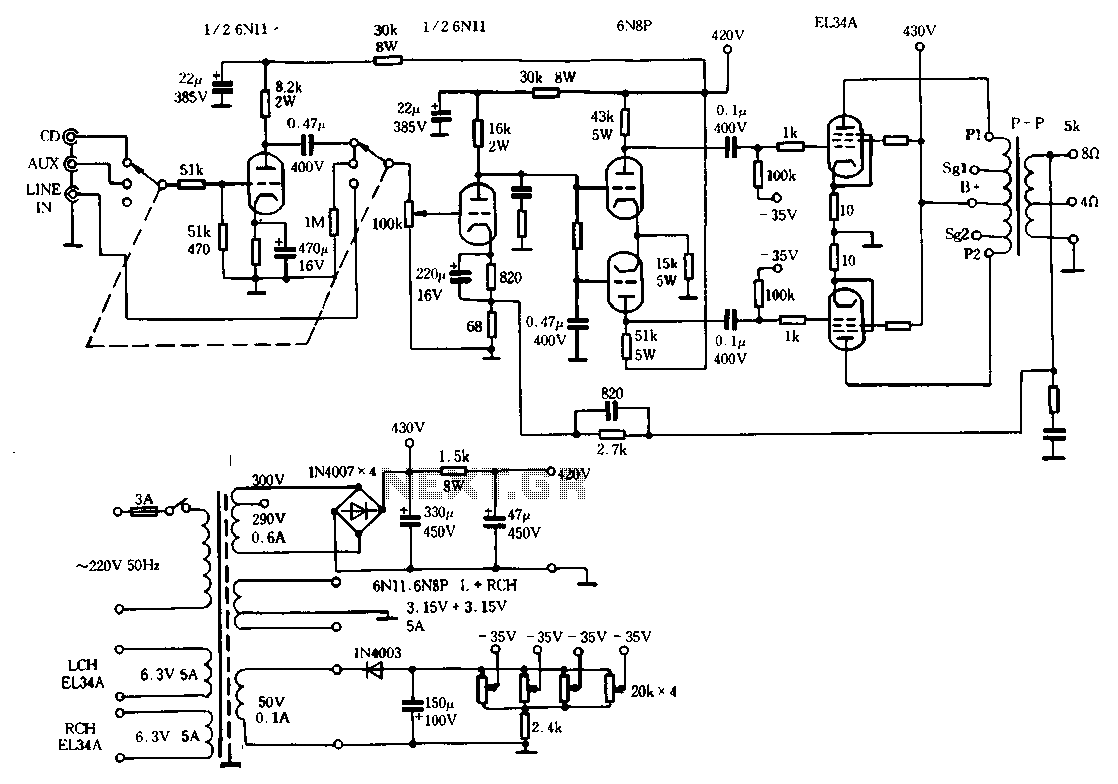
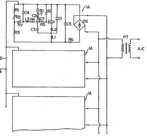
The Ml00 circuit is a typical tube circuit, functioning as a preamplifier. Its input stage utilizes a common cathode amplifier, followed by an inverter stage, culminating in a power amplifier that has been enhanced from a standard connection. This...
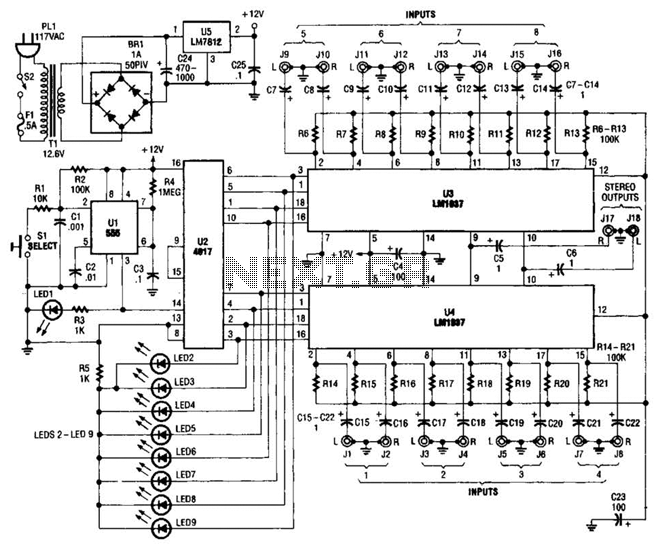
This source is selected by pressing a momentary-contact pushbutton switch (SI). Switch SI is connected to the trigger of a 555 oscillator/timer (U1) configured as a monostable multivibrator, which generates one short output pulse for each press of SI....

This circuit utilizes a 4049 integrated circuit (IC) to control a 2N2222 switching transistor. The transistor, in turn, drives a piezo transducer known as crystal 1. The circuit design begins with the 4049 IC, which is a hex inverter capable...
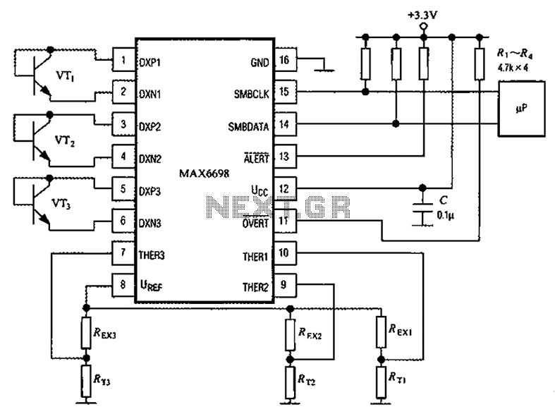
Channel 7 presents a circuit diagram of a smart temperature sensor using the MAX6698. This circuit includes three transistors (VT1, VT2, and VT3) and three thermistors (RT1, RT2, and RT3). An internal reference voltage source is provided via resistors...